GPS/IMU Sensor
1. Data Flow Overview
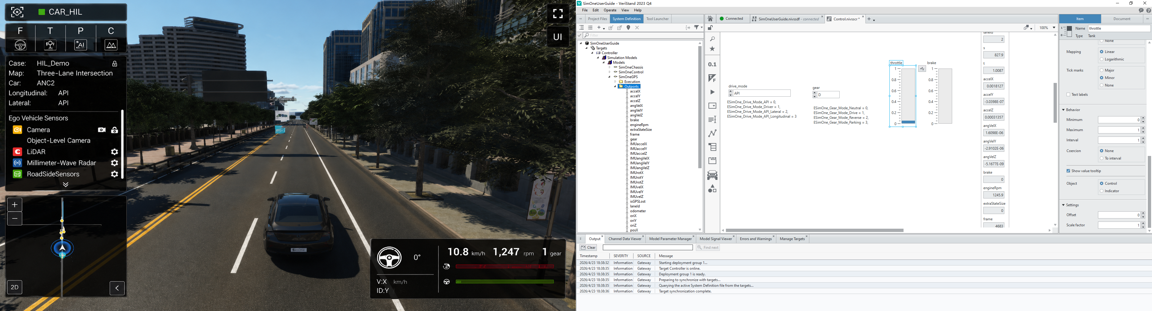
The GPS/IMU simulation data flow begins at SimOne's localization and inertial module. It generates localization and motion data that reflects the characteristics of real GPS/IMU sensors, transmits the data to the real-time target via Ethernet, and then delivers it to the ECU via the automotive bus for localization and sensor fusion algorithms. The data flow design must ensure that localization accuracy, motion state authenticity, and latency meet the requirements of closed-loop control.
2. SimOne Configuration
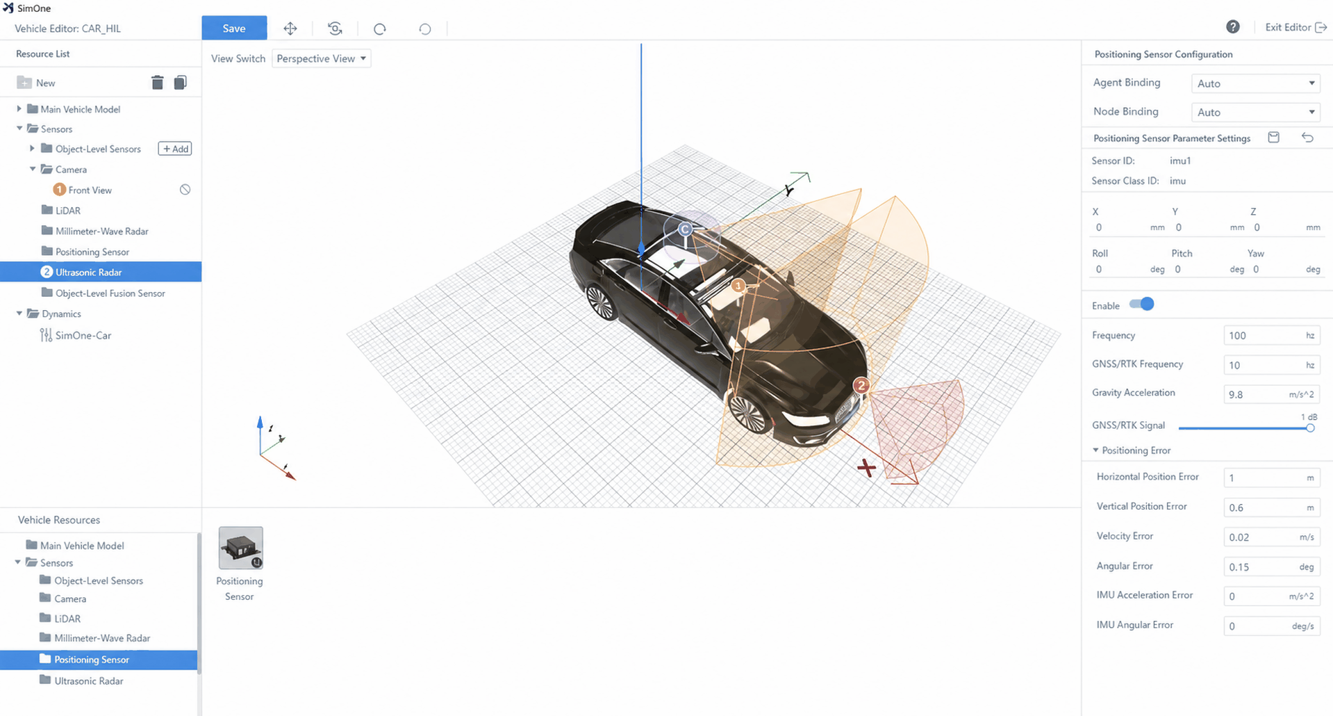
(1) Select the ego vehicle and add a localization sensor;
(2) Select the GPS/IMU Sensor;
(3) Run the use case
Select a use case and run the corresponding ego vehicle use case to ensure the GPS/IMU sensor generates simulation data correctly;
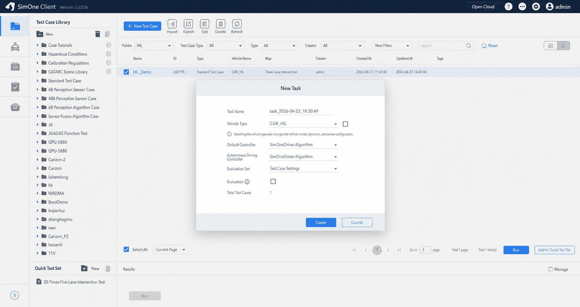
(4) Run Trans
3. Real-Time Target Configuration
(1) Load the SimOneGPS model
- Select Simulation Model;
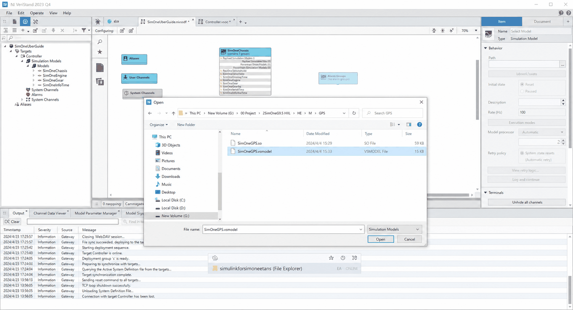
- Browse and select the SimOneGPS model file;
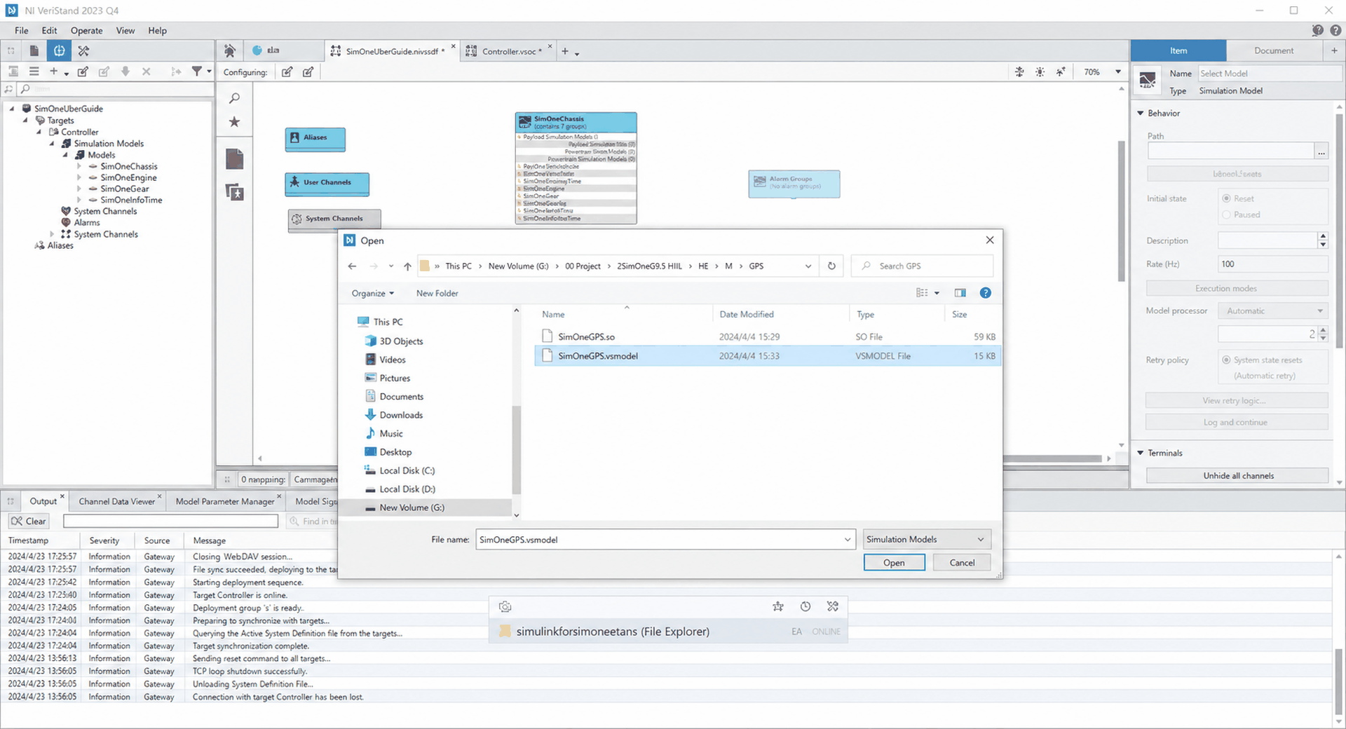
- Load the SimOneGPS model into the VeriStand project;
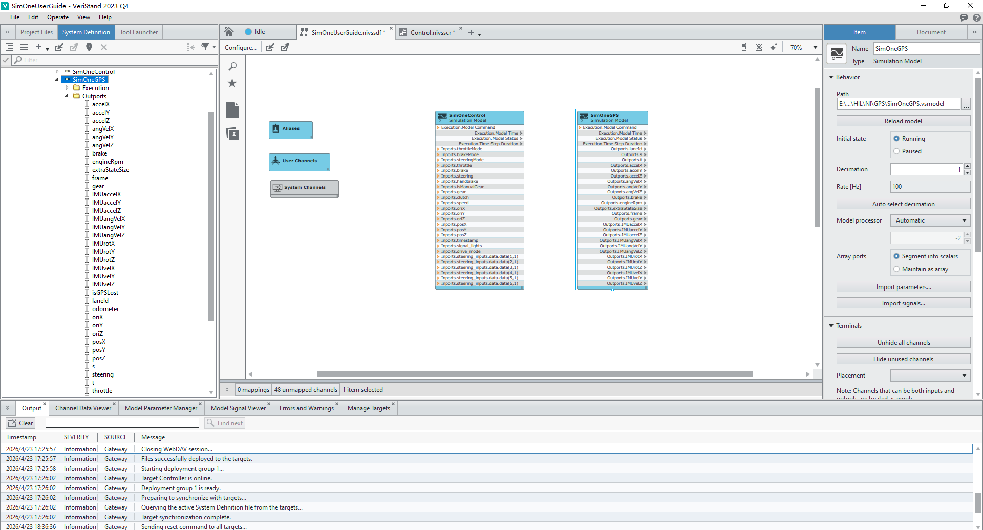
(2) Deploy the SimOneGPS model
Deploy the VeriStand project to ensure the SimOneGPS model can correctly receive the GPS/IMU simulation data sent by the Trans tool;
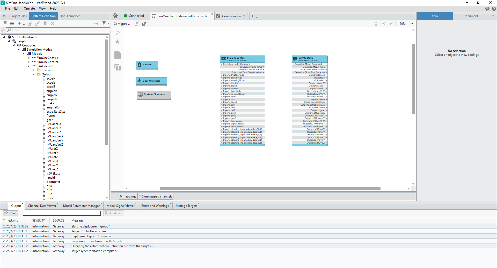
(3) Verify GPS/IMU data
Use the monitoring window in VeriStand to view signals in the SimOneGPS model. Verify the accuracy and latency of the GPS/IMU data to ensure it meets the input requirements of the ECU localization and fusion algorithms;