Distributed System UI Overview
Distributed System UI Overview
This page describes the UI layout and feature areas of the distributed system. For the distributed system configuration process, refer to Distributed System Configuration.
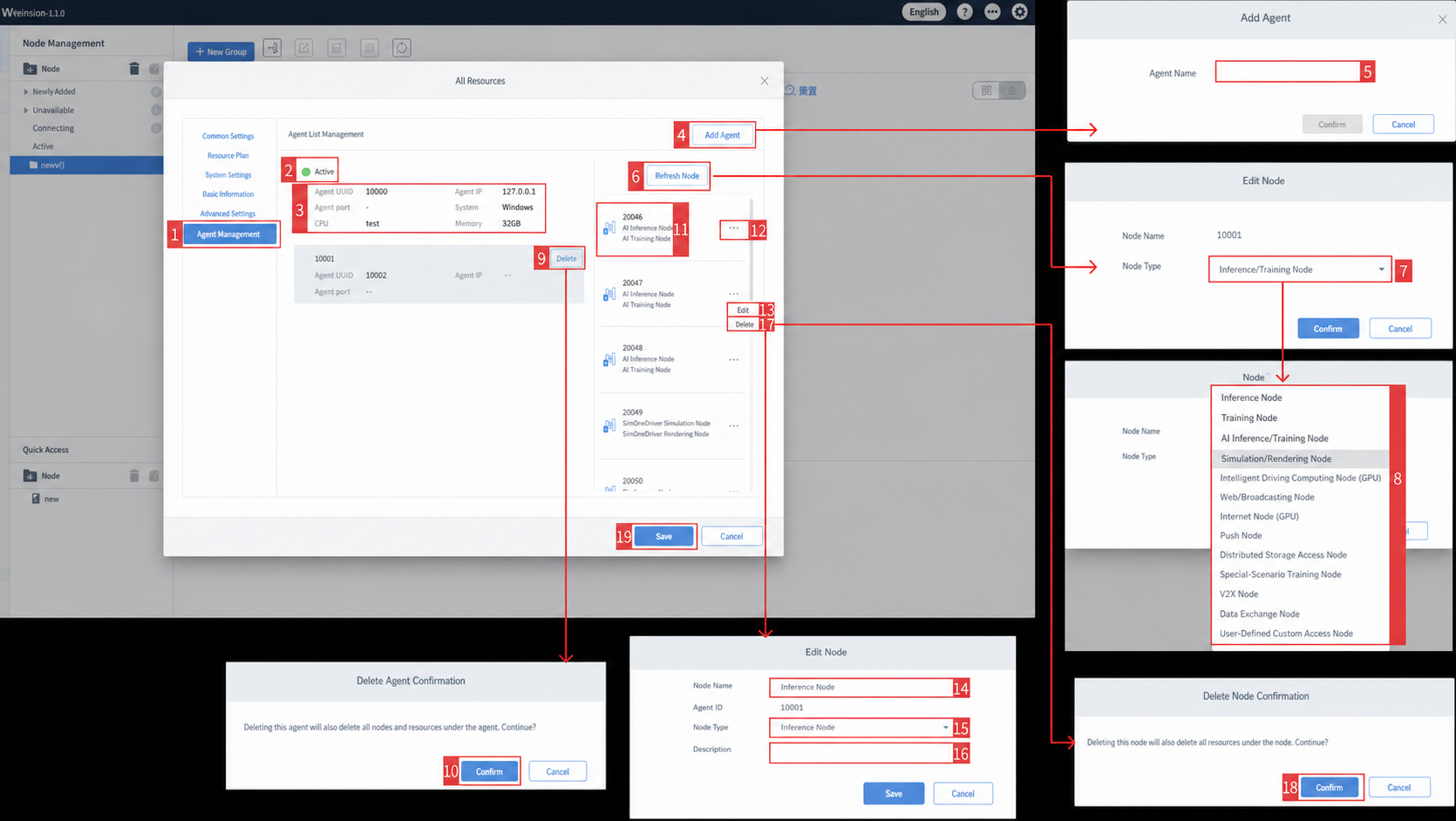
| ID | Item | Description |
|---|---|---|
| 1 | Global Settings Module Switch | Includes General Settings, Visualization Tools, System Settings, System Info, System Configuration, and Agent List. Click Agent List to manage Agent entries. |
| 2 | Agent Name and Online Status | Displays the name of each added Agent and its online/offline status. |
| 3 | Agent Detail Panel | Shows detailed Agent information including Agent UUID, Agent IP, Agent Port, System, CPU, and Memory. |
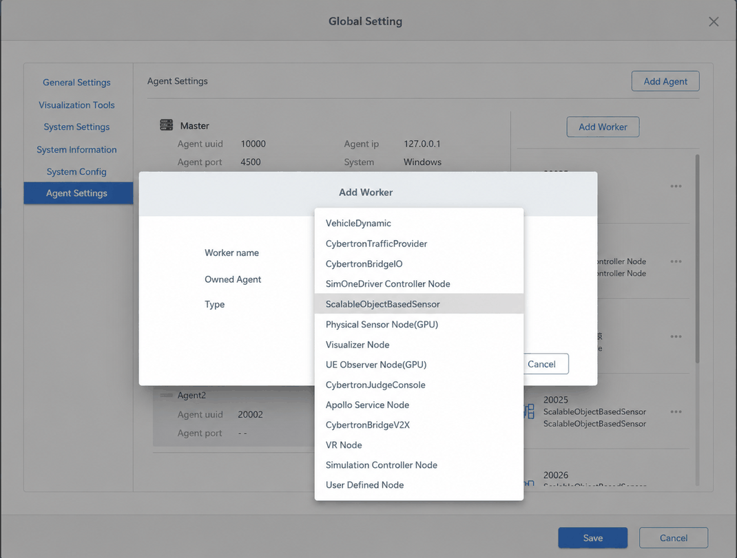
| 4 | Add Agent Button | Click to open the Add Agent dialog. |
| 5 | Agent Name | Enter the Agent name in the dialog and click Create to add a new Agent. |
| 6 | Add Node Button | Click to open the Add Node dialog, where you can enter a node name and select a node type. |
| 7 | Node Name Input | Enter the node name. |
| 8 | Node Type Selection | The dropdown includes the following options: Dynamics Node, Dynamic Simulation Node, API Service Node, SimOneDriver Controller Node, Object-Level Sensor Node, Physics-Level Sensor Node (GPU), Web Visualization Node, Visualization Node (GPU), Judgment Node, Apollo Control Interface Node, V2X Node, VR Node, Simulated Controller Node, User-Defined Interface Node. |
| 9 | Delete Node | Click to open the Delete Node confirmation dialog. |
| 10 | Delete Agent Dialog | Click Confirm to delete the selected Agent. |
| 11 | Node Info List | Displays node ID and node name. |
| 12 | More Options | Click to reveal two buttons: Edit and Delete. |
| 13 | Edit Button | Click to open the Edit dialog. |
| 14 | Node Name | Edit the node name here. |
| 15 | Node Type Selection | Click to open the dropdown and change the node type. |
| 16 | Startup Command | Command-line parameters for starting UE on Visualization (GPU) and Physics-Level Sensor nodes (sets window position, resolution, GPU, etc.). See Sensor Distributed Node — Edit Node Visualization Window Startup Parameters. |
| 17 | Delete Node Button | Click to open the Delete Node confirmation dialog. |
| 18 | Delete Node Confirm | Click Confirm in the Delete Node dialog to delete the node. |
Agent Launcher
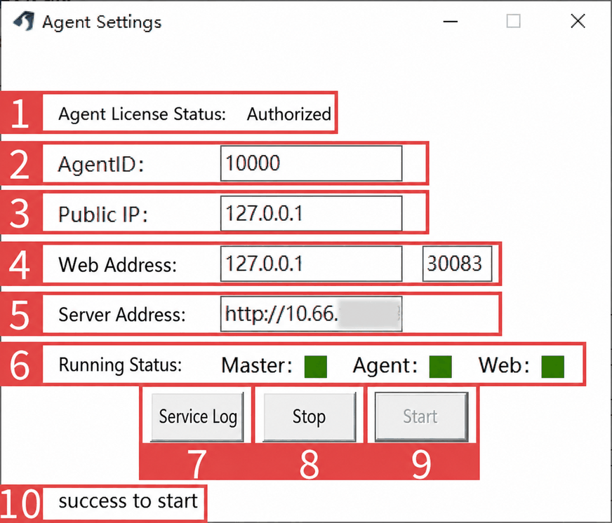
| ID | Item | Description |
|---|---|---|
| 1 | Agent Authorization Status | Displays either Authorized or Unauthorized. |
| 2 | Agent ID | The authorization code for this Agent. |
| 3 | Public IP | The IP address of the network interface bound to the Agent. |
| 4 | Web IP Address and Port | The IP address of the Master host in the distributed cluster. |
| 5 | Server Address | The external access address of the deployed server. |
| 6 | Service Status | Green indicates the service is running normally; red indicates an error. |
| 7 | Service Log | Click to open the Foundation log folder. |
| 8 | Stop Button | Click to toggle the Agent between online and offline. |
| 9 | Start Button | Click to bring an offline Agent back online. |
| 10 | Startup Status | Displays one of two states: success to start or failed to start. |
Distributed System
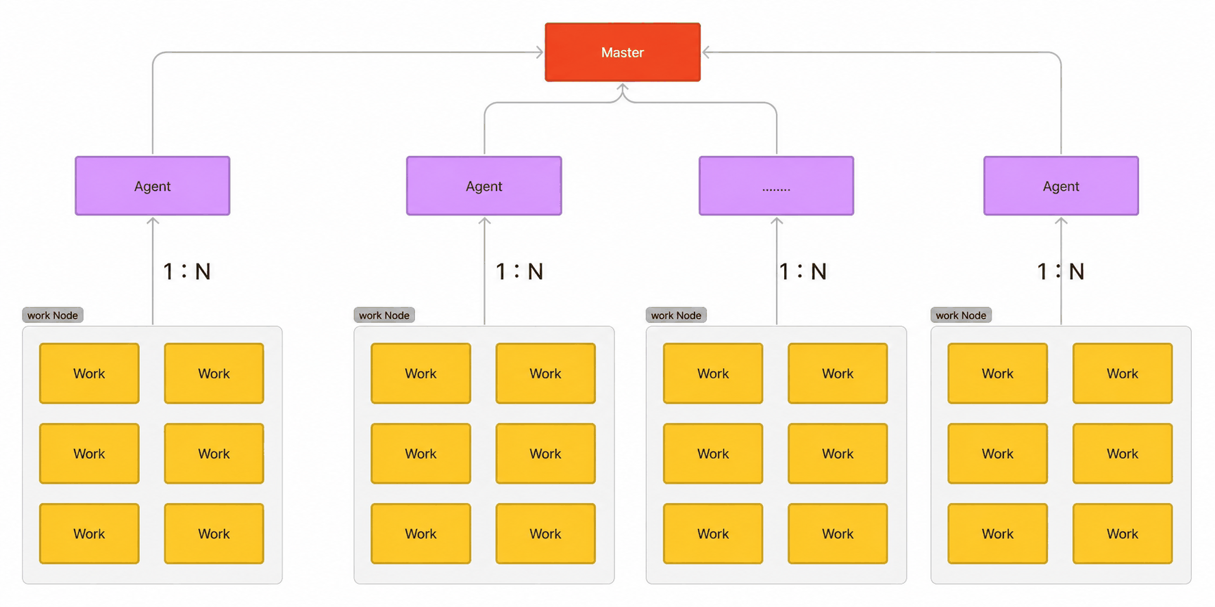
1. Architecture Diagram
2. Terminology
| Component | Description |
|---|---|
| Master | The core Master node, responsible for managing all Agents (add, delete, update, query). |
| Agent | The proxy node for a distributed node. |
| Work | An internally abstracted simulation worker node, such as Nodetimer, BridgeIO, VehicleDynamic, etc. |
3. Architecture Overview
The distributed architecture uses a master-slave model. Master is the core node that manages all Agents. Each machine (or Docker container) can have only one Agent, so adding an Agent is equivalent to adding the resources of one machine.
- An Agent is responsible for managing (add/delete/update/query) and starting/stopping Work nodes. Each Agent can manage multiple Work nodes of different types, and users can freely choose which Work nodes to enable under each Agent.
- Work nodes are dedicated workers responsible for specific functions — for example, Nodetimer is the timing service node, BridgeIO is the API data I/O node, and VehicleDynamic is the dynamics node.
4. Why Configure Nodes and Agents
(1) Resource scaling: A single machine has limited resources. A distributed architecture allows horizontal scaling.
(2) User-configurable: Users can choose how many Agents to add and which Work nodes to enable under each Agent, providing maximum flexibility.
(3) Cross-platform: Whether on Windows or Linux, machines can easily join the distributed architecture. A single Docker container can also act as an Agent, ensuring broad platform compatibility.
5. Use Cases
(1) Multi-vehicle interaction: Each Agent is configured with one Ego Vehicle, enabling interactions between vehicles.
(2) High-fidelity rendering: A single machine's GPU may not support multiple cameras or UE high-fidelity rendering. Distributing UE and cameras across multiple Agents makes full use of each machine's GPU, enabling multi-camera and multi-UE high-fidelity rendering.
6. Choosing Nodes and Agents
In the Agent List, you can add, delete, update, and query Agents. Each machine (or Docker container) is one Agent with a unique Agent UUID. When an Agent connects successfully, its IP address is displayed.
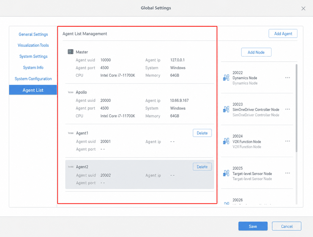
Under each Agent, you can select from the node types listed above. In general, the choice of node type depends on the intended purpose of the Agent.
Example
For example, if an Agent is used for high-fidelity rendering, add a Visualization Node (GPU) and a Physics-Level Sensor Node (GPU) under it. You can add one or more nodes of each type as needed, and remove any nodes that are not required.
Common node type recommendations:
| Use Case | Recommended Node Types |
|---|---|
| Algorithm integration (C++/Python API) | API Service Node |
| Apollo algorithm integration | Apollo Control Interface Node |
| Custom algorithm integration | User-Defined Interface Node |
| Physics-level sensors (high-fidelity rendering, e.g., cameras, LiDAR point cloud) | Physics-Level Sensor Node (GPU), Visualization Node (GPU) |
| Object-level sensors (ground truth data) | Object-Level Sensor Node |
| Dynamics simulation | Dynamics Node |
| Scenario evaluation and judgment | Judgment Node |
| V2X | V2X Node |
7. Node Configuration Errors and Solutions
No work node
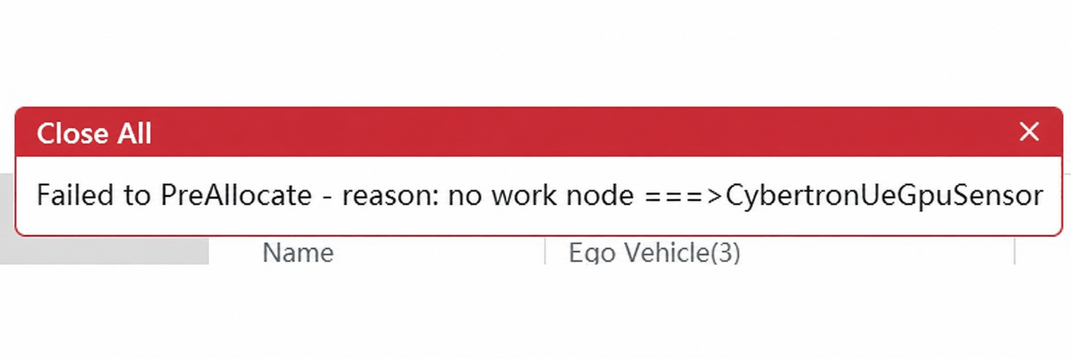
This error generally occurs when a node type is required but has not been added.
For example, if physics-level sensors are used but no Physics-Level Sensor Node has been added in the node configuration, this error appears.
The solution is to add a Physics-Level Sensor Node (GPU) in the Agent's node configuration, then restart the SimOne service (click Stop and then Start in the SimOneLauncher system tray).