MIL: Model-in-the-Loop Testing
1. Third-Party Software Co-Simulation Compatibility Statement
| Software | Compatible Versions | Notes |
|---|---|---|
| Matlab | 2018a and later versions | Versions from 2015–2018 require version conversion; earlier versions are not recommended. |
Use this tutorial to learn how to integrate other applications for co-simulation testing.
2. Matlab Co-Simulation
Related Documentation
For detailed interface parameters of each Simulink module, refer to Third-Party Middleware: Simulink.
This tutorial demonstrates how to connect Simulink to SimOne for co-simulation using an AEB algorithm as an example.
2.1 Video Tutorial
2.2 Steps
2.2.1 Edit the Test Case
2.2.1.1 Open the Test Case Library and Create a Standard Test Case
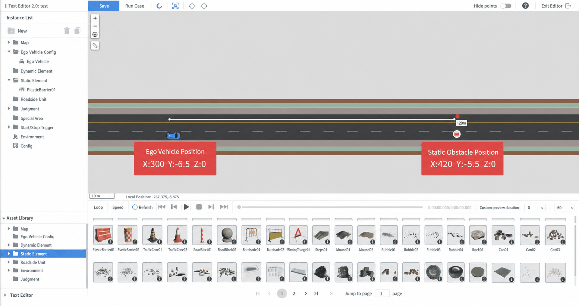
- In the test case editor, use the default map — Three-Lane Intersection — and drag in an Ego Vehicle.
- The Ego Vehicle world coordinates are X: 300, Y: -6.5, Z: 0. These coordinates are for reference only; you may customize the Ego Vehicle position.
- Place a static obstacle Water Horse 01 120 meters ahead of the Ego Vehicle in the same lane at X: 420, Y: -5.5, Z: 0. Then click Save in the upper-left corner of the editor.
2.2.1.2 Launch and Configure Matlab
Launch Matlab locally and follow the steps below to establish communication between Matlab and SimOne.
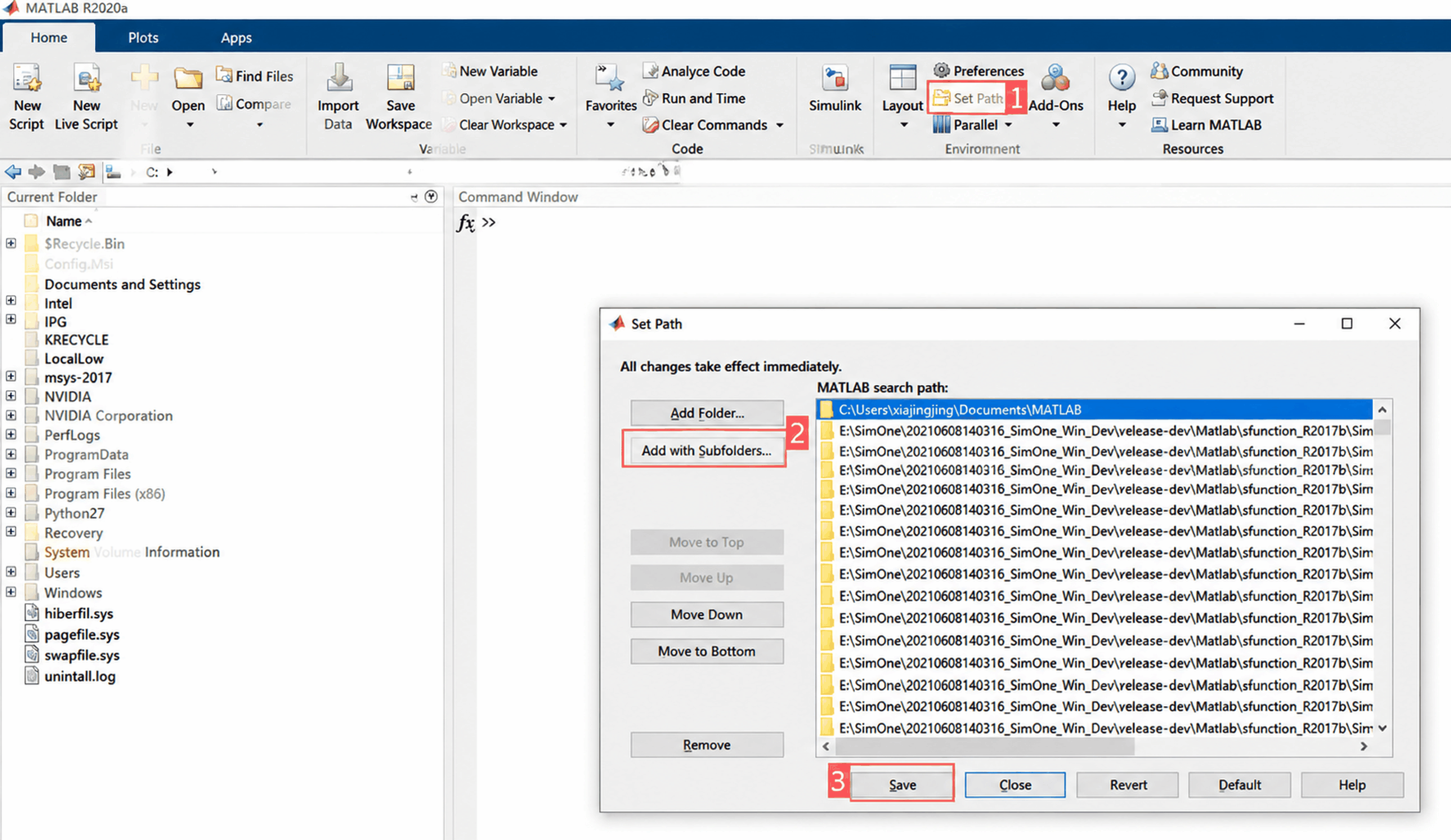
(1) Click Set Path, follow the numbered steps in the figure, select Add with Subfolders, switch the Matlab directory to SimOneAPI/Matlab/sfunction_R2018a/SimOneModule, and click Save.
(2) Set the current folder on the left to SimOneAPI/Matlab/sfunction_R2018a/SimOneModule.
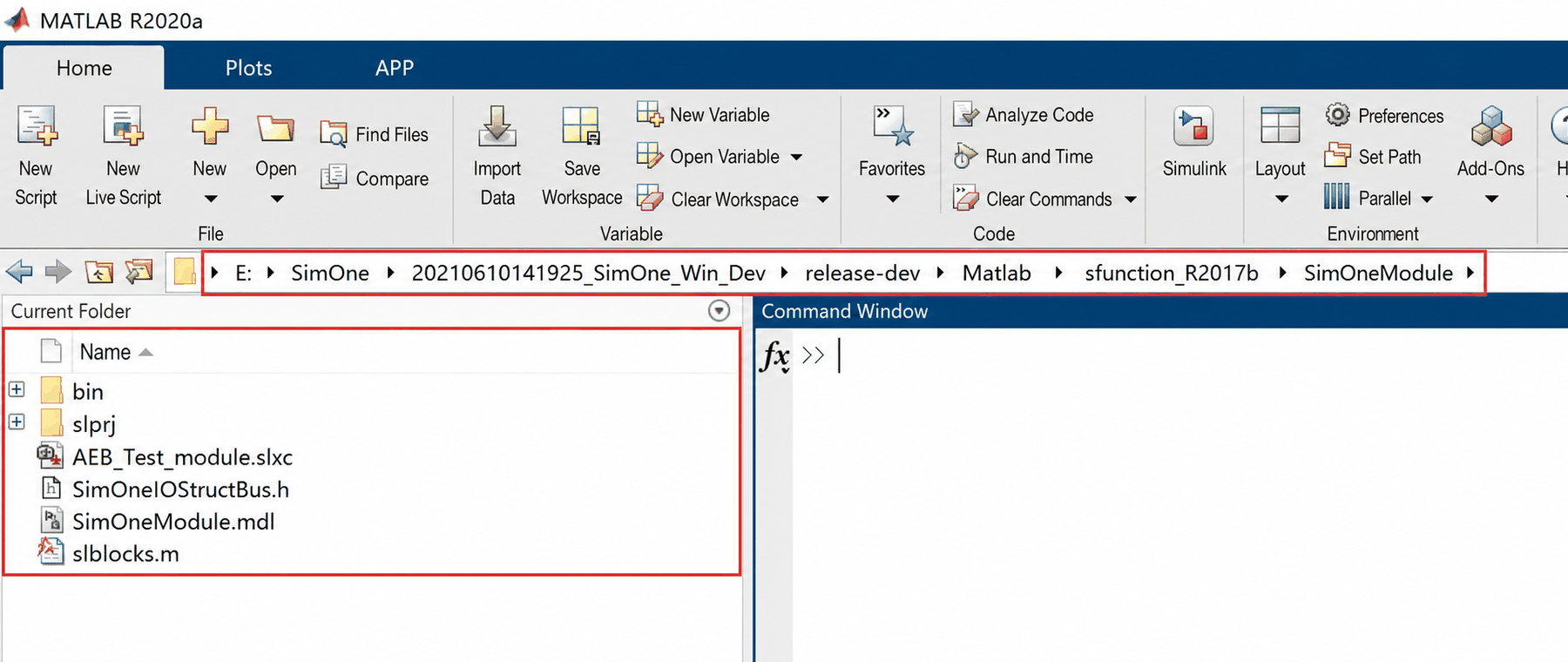
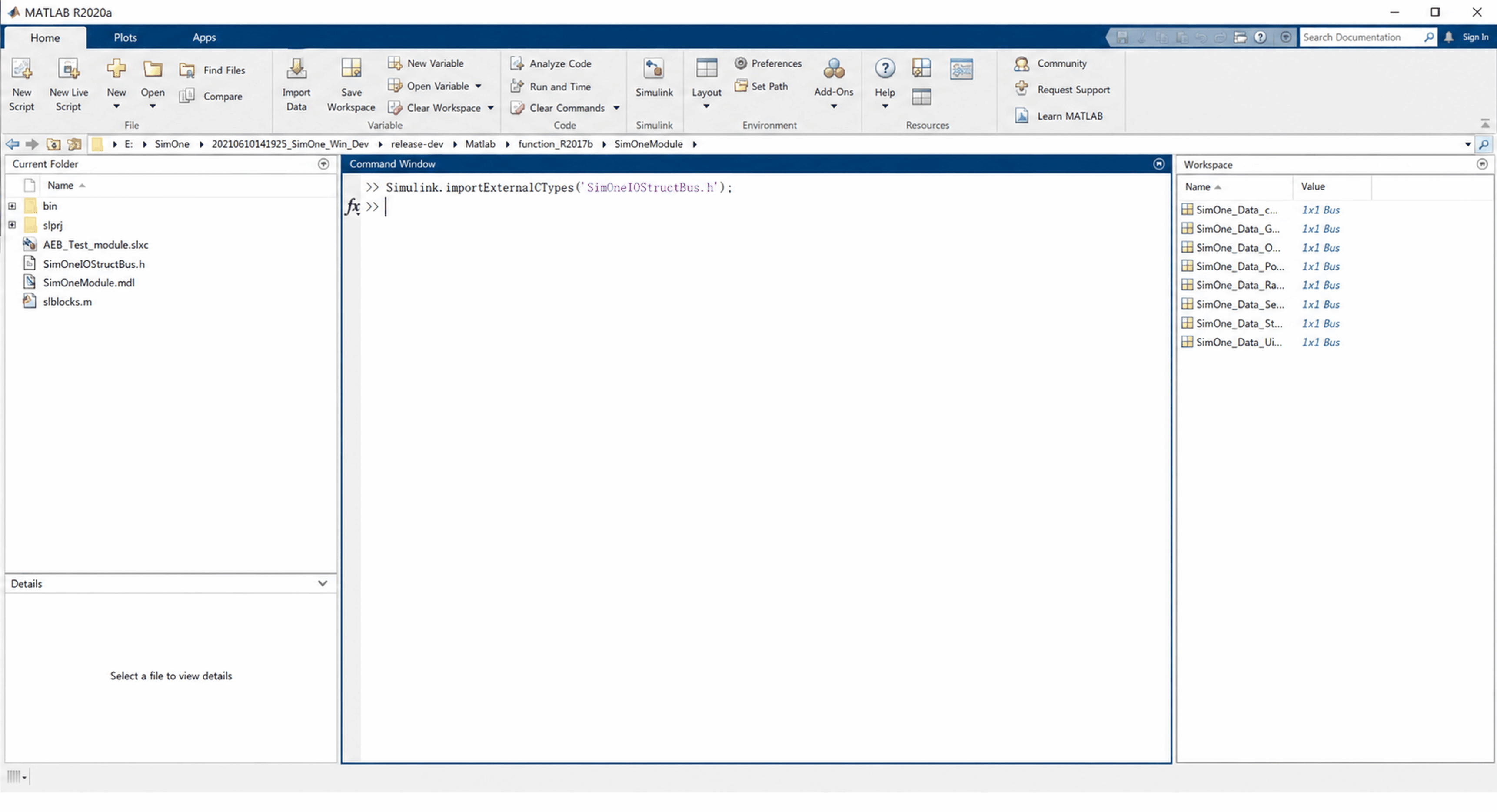
(3) Create bus signals: run Simulink.importExternalCTypes('SimOneIOStructBus.h') in the command window.
As shown below, the bus signals appearing in the workspace on the right confirm successful creation.
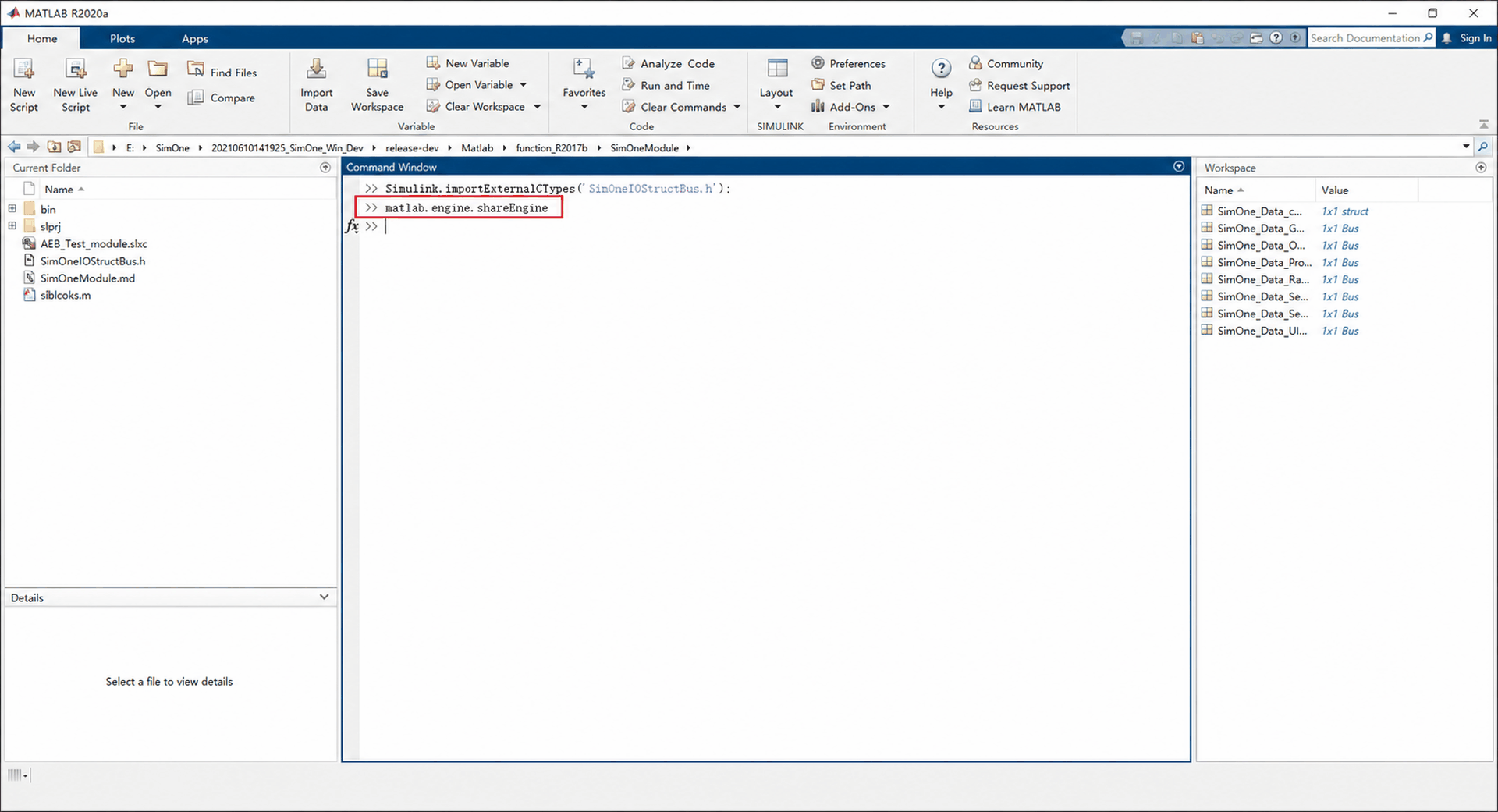
(4) Create a communication connection: run matlab.engine.shareEngine in the command window.
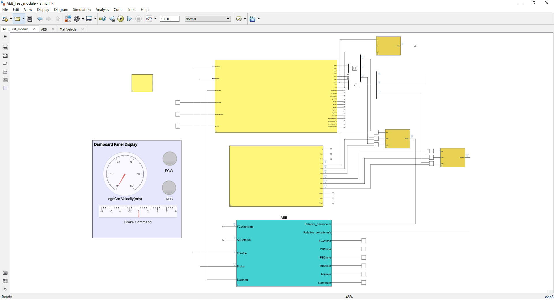
(5) Open the AEB sample provided by SimOne: SimOneAPI/Matlab/sfunction_R2018a/Examples/AEB/AEB_Test_module.slx
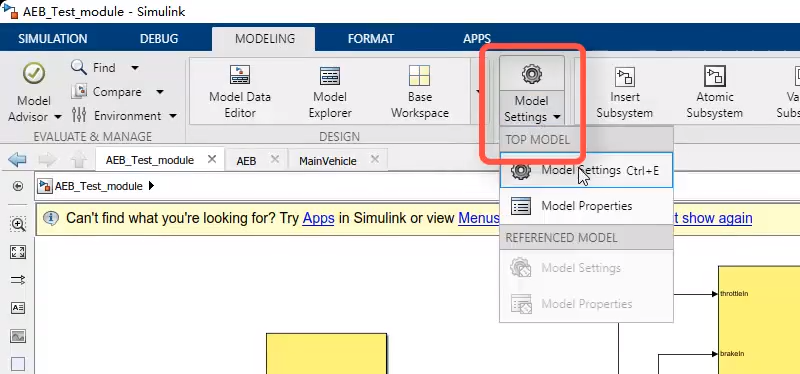
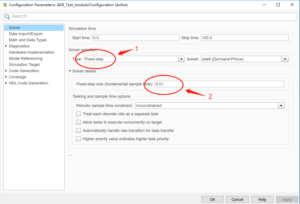
(6) Set the Simulink simulation Sample Time. In the Simulink project, click Simulation → Model Configuration Parameters, and set the Solver selection Type to Fixed-step.
The Time Synchronization Module includes a switch for frame-sync mode, which is enabled by default. If frame-sync mode is used, set the Fixed-step size to match the SimOne run frequency — for example, set it to 1/60 when SimOne runs at 60 Hz.
If frame-sync mode is not used, it is recommended to set the Fixed-step size slightly larger than the SimOne run frequency — for example, set it to 1/100 when SimOne runs at 60 Hz and Simulink runs at 100 Hz.
2.2.1.3 Run the Co-Simulation
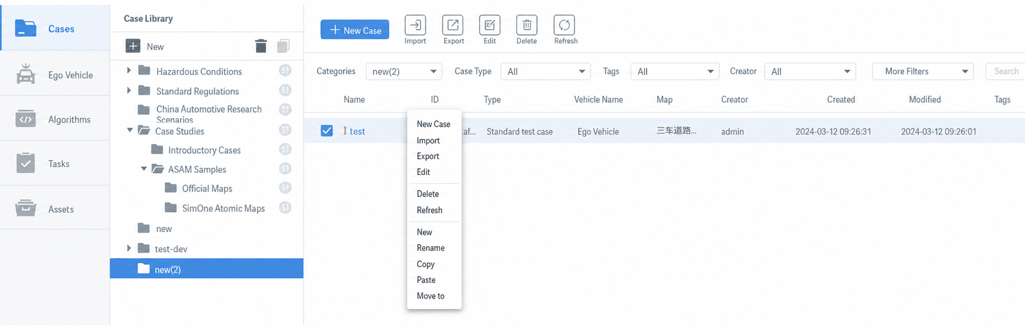
(1) Return to the SimOne test case library, select the test case saved in Step 5, and copy-paste it.
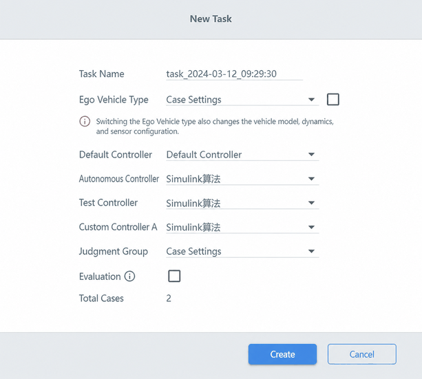
(2) Click Run; keep the Ego Vehicle type as Test Case Setting.
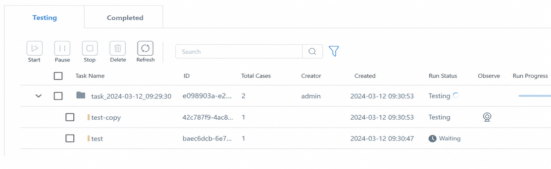
(3) Open Task Management → Running list and click the camera icon to open the observer viewport.
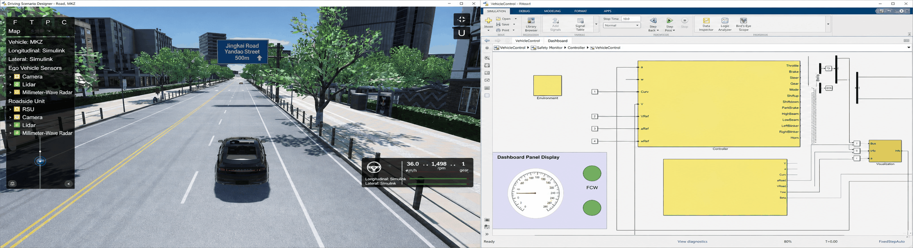
(4) You can now see Simulink and SimOne running in co-simulation.
3. Third-Party Dynamics Co-Simulation Workflow
3.1 Front-End Configuration
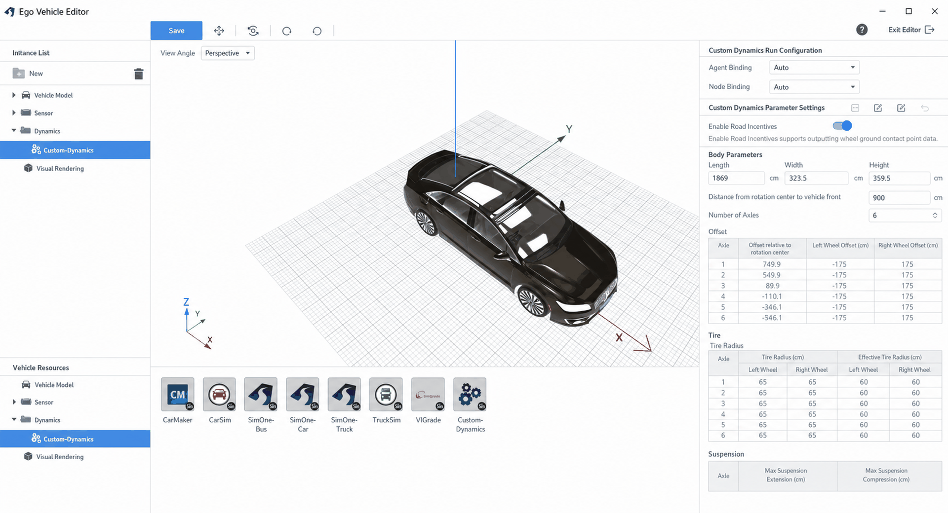
Open SimOne and select Custom Dynamics in the Ego Vehicle editor, then modify the corresponding parameters. For a standard passenger vehicle, set the number of axles to 2 and adjust other parameters accordingly. The coordinate origin of the third-party dynamics is the rotation center.
3.2 Middleware Configuration and Build
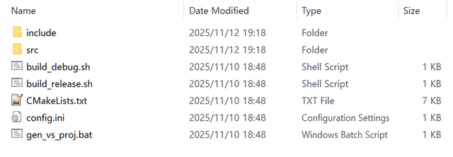
The test program is located in the \SimOneAPI\SimOneTrans* directory. Run gen_vs_proj.bat or build_release.sh* to generate the code.
Input parameters:
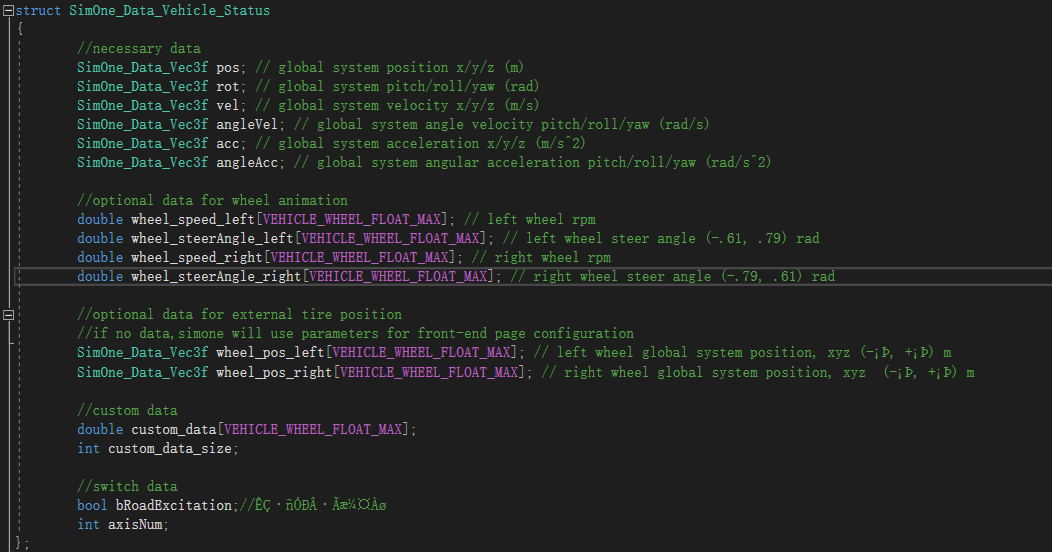
Output parameters:

3.3 Communication Configuration
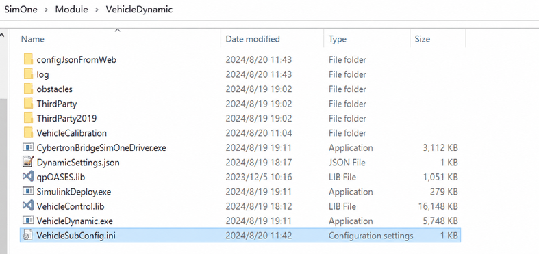
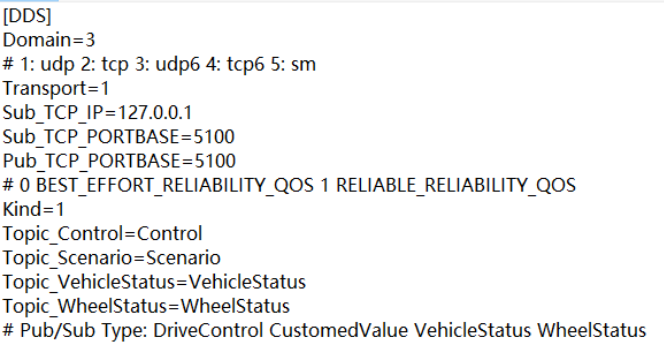
The dynamics communication configuration file VehicleSubConfig.ini is located at the path shown below.
Ensure that the Domain port in VehicleConfig.ini matches the Domain port in the middleware's config.ini.