LiDAR Details
1. Overview
The LiDAR model is based on ray-tracing technology (Ray Tracing), simulating the emission, propagation, and reflection of laser beams to output high-precision 3D point-cloud data. It supports mechanically rotating scan simulation with customizable beam distribution.
2. Quick Start: Custom Mechanical-Scan LiDAR Model
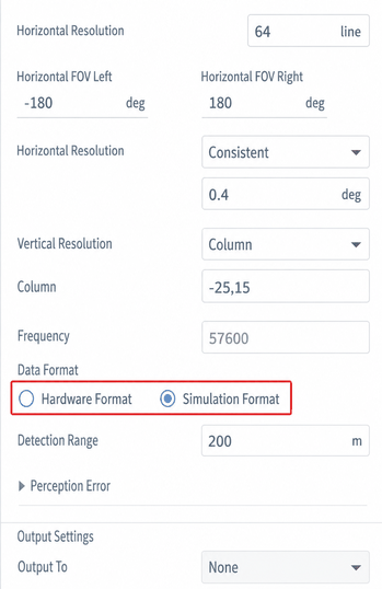
Output format descriptions:
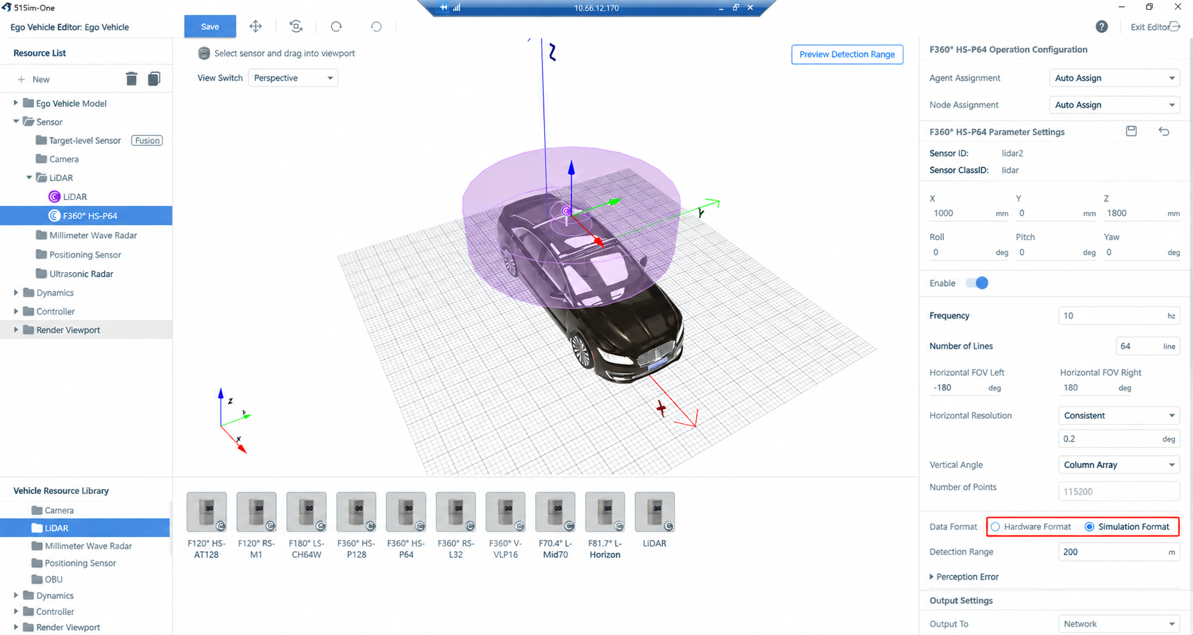
- Hardware Format: Sends LiDAR data to the customer's algorithm using the data-packet format defined for the original radar model. Each radar model has its own protocol; typically used for HIL simulation testing.
- Simulation Format: SimOne's custom LiDAR data format with a unified packet type and consistent point format for all radars; typically used for SIL simulation testing.
2.1 Prerequisites
- Horizontal resolution is uniform (equal spacing).
- Number of beams is below 128 (internal limit).
- Vertical pitch angles can be uniformly distributed or individually specified for each beam.
2.2 Steps
(1) Open the SimOne Ego Vehicle Editor and configure the LiDAR sensor.
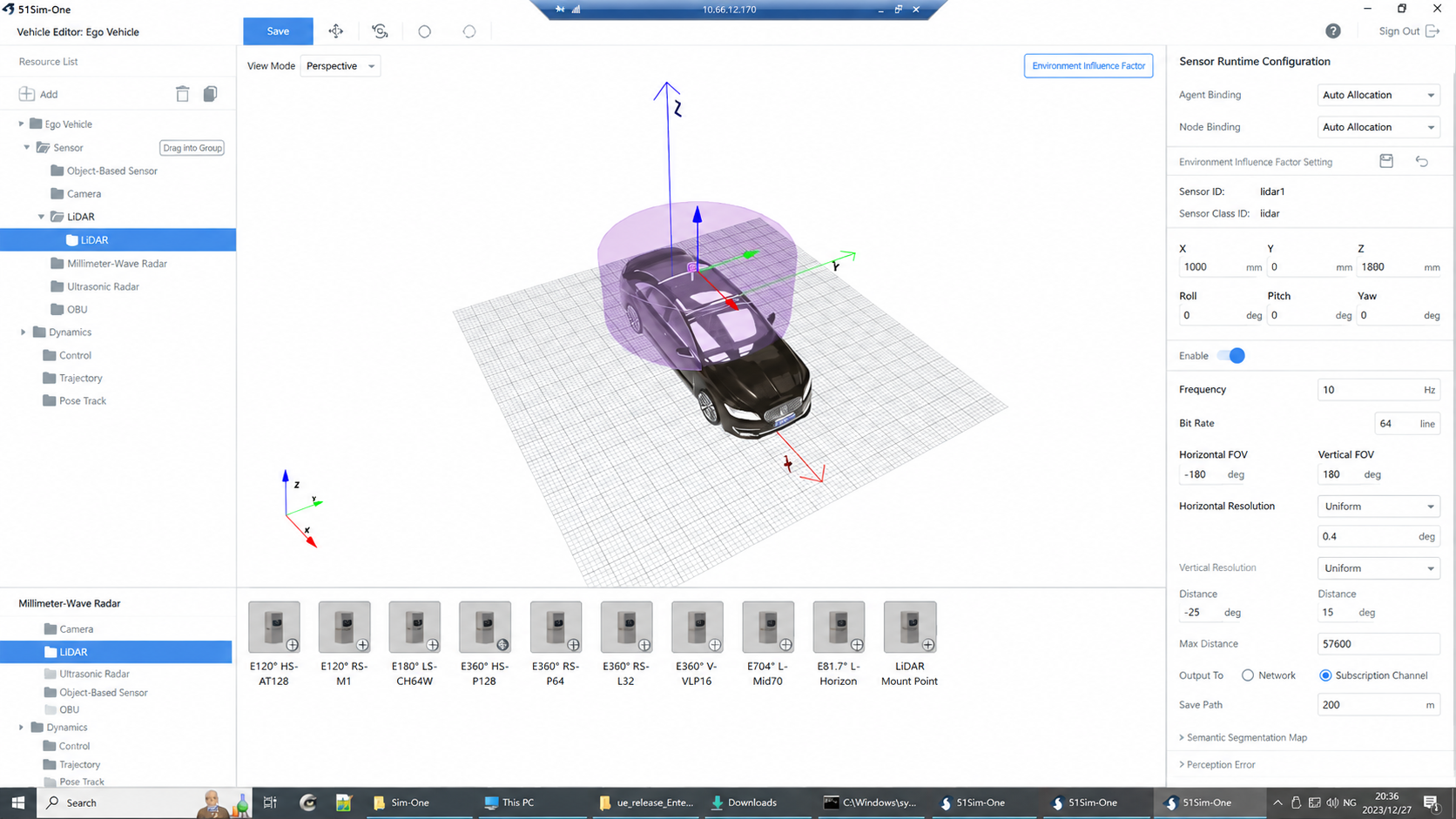
(2) Configure horizontal and vertical FOV.
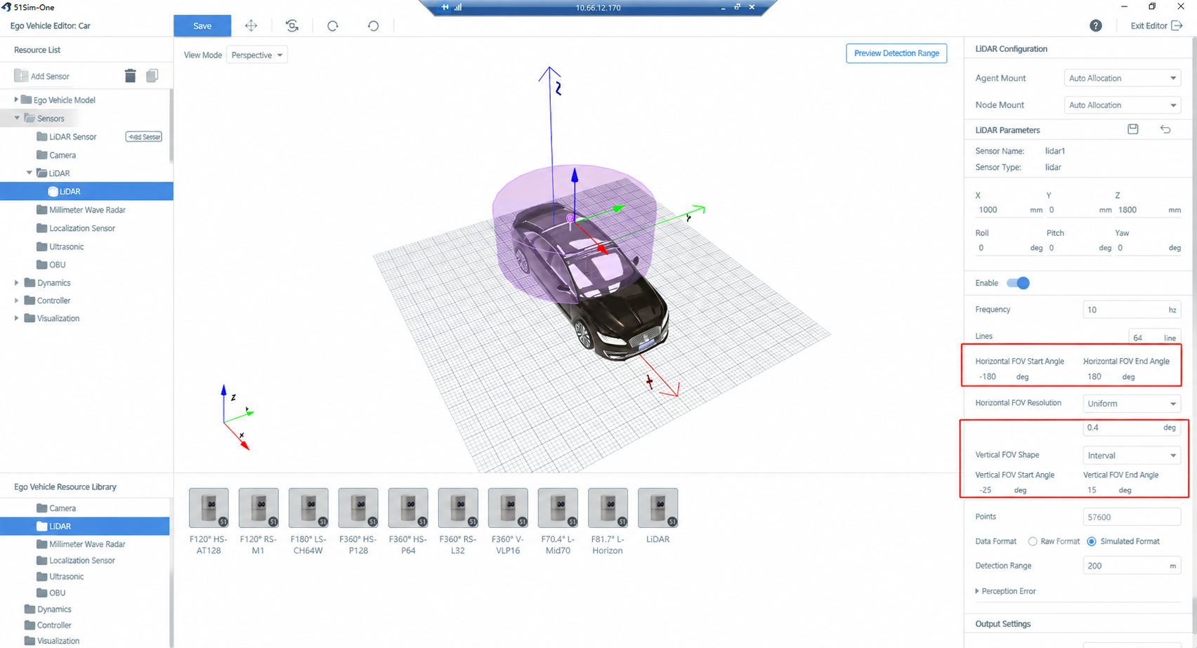
(3) For non-uniform vertical scan mode, specify the angle for each beam individually by entering the angles in the list.
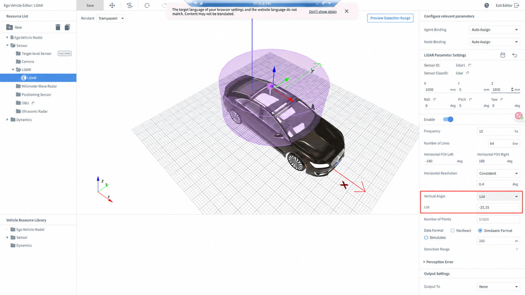
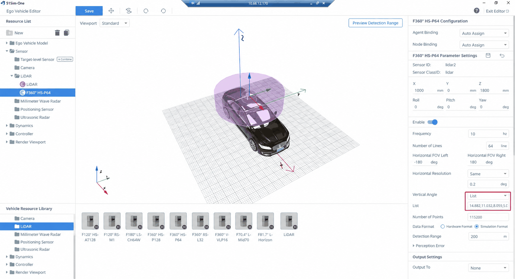
(4) Example: the vertical angles for the hs-pandar64 LiDAR (top to bottom) are:
14.882,11.032,8.059,5.057,3.04,2.028,1.86,1.688,1.522,1.351,1.184,1.013,0.846,0.675,0.508,0.337,0.169,0,-0.169,-0.337,-0.508,-0.675,-0.845,-1.013,-1.184,-1.351,-1.522,-1.688,-1.86,-2.028,-2.198,-2.365,-2.536,-2.7,-2.873,-3.04,-3.21,-3.375,-3.548,-3.712,-3.884,-4.05,-4.221,-4.385,-4.558,-4.72,-4.892,-5.057,-5.229,-5.391,-5.565,-5.726,-5.898,-6.061,-7.063,-8.059,-9.06,-9.885,-11.032,-12.006,-12.974,-13.93,-18.889,-24.897
(5) For the custom LiDAR scan model, select Simulation Format as the data format. Point-cloud data can then be received via SimOne's API interface.
2.3 FAQ
Private Protocol Adaptation:
Q: If I want to implement my own point-cloud protocol, which APIs should I use and how do I retrieve the data to fill and pack it myself?
A:
- Obtain standard SimOne point-cloud data via the SimOne API and perform secondary encapsulation.
- Key API interfaces:
- Active retrieval:
GetStreamingPointCloud - Callback reception:
SetStreamingPointCloudUpdateCB
- Active retrieval:
3. Appendix: Simulation Parameter Reference
3.1 Core Parameter Summary
| Parameter Category | Core Parameter | Function Description | Details Reference |
|---|---|---|---|
| Geometry | Mounting Position & Angle | Defines the sensor's spatial pose in the vehicle coordinate system (X, Y, Z, Roll, Pitch, Yaw). | See [Common Sensor Parameters — Basic Information] |
| Operating Mode | Update Frequency | Sensor data refresh rate (e.g., 10 Hz, 20 Hz), determining point-cloud update speed. | See 2.3.1 Basic Information |
| Performance | FOV (Field of View) | Includes horizontal FOV and vertical angle range, jointly defining the detection envelope. | See 2.3.1 Basic Information |
| Beam Count & Resolution | Beam count determines vertical resolution; horizontal resolution determines the angular sampling interval. | See 2.3.1 Basic Information | |
| Maximum Detection Range | The farthest distance at which the radar can effectively detect a target. | See 2.3.1 Basic Information | |
| Simulation Fidelity | Perception Error | Simulates real radar measurement noise, such as point-cloud error and reflection intensity error. | See 2.3.2 Perception Error |
| Environmental Adaptation | Supports simulating radar performance under different lighting conditions and weather (rain/snow/fog). | Set via the test case editor environment settings | |
| Data Specification | Data Format | Select output format: Hardware Format (simulates a specific radar model protocol, for HIL testing) or Simulation Format (unified format, for SIL testing). | See 2.3.1 Basic Information |
| Data Output | Output Target | Configures the destination for simulation data, e.g., sent over the network or recorded to a Dump file. | See 2.4 Output Settings |
3.2 Input Parameters
3.2.1 Basic Information
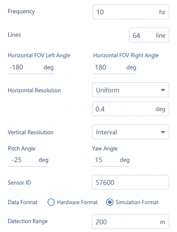
| No. | Parameter | Definition |
|---|---|---|
| 1 | Frequency | Number of rotations or scans per second for the LiDAR; the refresh rate of the point-cloud data. |
| 2 | Beam Count | Number of laser beams in the vertical direction; determines vertical resolution. More beams produce denser point clouds. |
| 3 | Horizontal FOV Left / Right Angle | The horizontal field-of-view range; the horizontal scanning angle of the radar. |
| 4 | Horizontal Resolution | The angular interval between adjacent scan points in the horizontal direction; smaller values indicate higher resolution. • Uniform: Uniform angular resolution across the entire horizontal FOV — the most common mode, suitable for simulating standard mechanical rotating LiDAR. • List: Allows specifying custom angular resolution for different zones within the horizontal FOV. This non-uniform resolution mode is suitable for simulating certain solid-state LiDARs (e.g., Flash, MEMS) or achieving region-of-interest (ROI) scanning to optimize computational resources. |
| 5 | Vertical Angle | The vertical scanning range, defining the upper and lower angle boundaries. • Range: Defines a continuous scanning range via "minimum vertical angle" and "maximum vertical angle" parameters (e.g., −25° ~ +15°). • List: Directly specifies the exact pitch angle for each scan beam via a list, suitable for LiDAR models with non-uniform beam distribution. |
| 6 | Point Count | Total number of points generated per scan; determined jointly by frequency, beam count, and resolution. |
| 7 | Data Format | LiDAR data source mode: • Hardware Format: Data sent using the packet format of the original radar model; each model has its own protocol; typically for HIL testing. • Simulation Format: SimOne's custom format with a unified packet type and point format; typically for SIL testing. |
| 8 | Detection Range | Maximum ranging capability; targets beyond this distance return no valid points. |
3.2.2 Perception Error
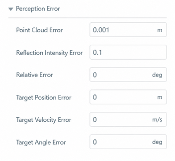
| No. | Parameter | Definition |
|---|---|---|
| 1 | Point Cloud Error | Point-cloud range error; simulates measurement distance uncertainty. |
| 2 | Reflection Intensity Error | Simulates target reflectivity measurement deviation; used to test perception stability. |
| 3 | Phase Error | Phase error from laser emission-to-reception timing differences; affects range accuracy. |
| 4 | Target Position Error | Deviation between the radar-measured target position and the actual position. |
| 5 | Target Velocity Error | Deviation between the radar-estimated target velocity and the actual velocity. |
| 6 | Target Angle Error | Difference between the radar-identified target direction and the true direction. |
3.3 Output Settings
LiDAR simulation data supports two output destinations: Network (real-time transmission via UDP/TCP) and Dump (recorded to local files).
3.3.1 Output to [Network]
| No. | Parameter | Definition |
|---|---|---|
| 1 | Subscription Channel | Network address and port at which point-cloud data is published, for algorithm modules or external programs to subscribe and receive. |
| 2 | Device Info Channel | Communication channel publishing device status information (e.g., timestamp, frame number, sensor pose). |
3.3.2 Output to [Dump]
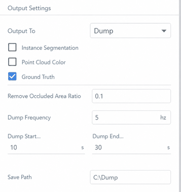
| No. | Parameter | Description |
|---|---|---|
| 1 | Instance Segmentation | Whether to output instance segmentation results (e.g., masks for different objects) |
| 2 | Point Cloud Color | Whether to retain point-cloud color information |
| 3 | Ground Truth | Whether to output ground truth (e.g., true obstacle positions and velocities) |
| 4 | Occlusion Area Ratio Filter | Filters output data — e.g., objects with more than 10% occlusion area are not output |
4. Appendix: Simulation Principles
4.1 Simulation Principles and Process Overview
LiDAR simulation generates virtual point-cloud data for algorithm testing by emulating the physical scanning process of a real sensor.
The core principle is: emit laser rays into the scene, compute their intersection points with objects, calculate reflection intensity based on intersection attributes (e.g., material), and then output a point cloud with spatial-temporal information after superimposing a noise model.
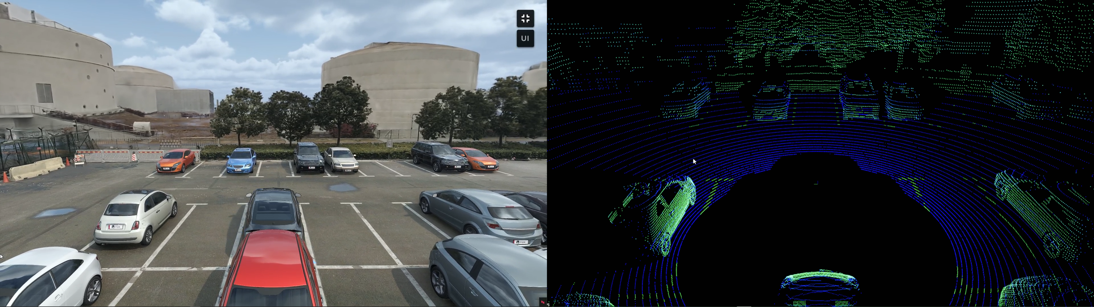
The main simulation steps are:
- Emit Rays: Generate laser ray bundles based on beam count, resolution, and other parameters.
- Scene Intersection: Compute the intersection of each ray with objects in the 3D scene.
- Compute Attributes: Calculate point position and reflection intensity based on intersection distance, incidence angle, and object material reflectance.
- Add Noise: Introduce the configured perception error model (e.g., range noise, intensity noise) to simulate real sensor measurement uncertainty.
- Coordinate Transform: Convert the point cloud from the LiDAR coordinate system to the vehicle coordinate system and world coordinate system.
- Output Data: Output the final point-cloud data over the network or via file (Dump).
4.2 Simulation Details and Output Data
4.2.1 Valid Point Calculation and Efficiency Optimization
Valid Point Criterion: For a 64-beam mechanical LiDAR with 0.4° horizontal resolution and 120 m maximum range at 10 Hz, 576,000 rays are emitted per second; only rays whose intersection points are within the maximum detection range count as valid points.
- Data Generation: Valid points must return position and material type; the system computes the distance from point to LiDAR and the ray incidence angle, then generates a noisy point cloud with intensity values using a material intensity / noise model.
- Efficiency: Due to the large ray count (500,000+ per second) and complex intersection algorithms, CPU/GPU parallel computing is used to ensure real-time performance, with point clouds output to the perception system in real time.
4.2.2 Reflection Intensity Simulation Rules
- Influencing Factors: Directly related to the near-infrared reflectance of the material, also affected by obstacle distance and laser reflection angle.
- Simulation Configuration: Scene assets (roads, vehicles, pedestrians, etc.) require dedicated physical materials (with varying reflectance); the intensity model is derived from real LiDAR data and normalized to 0–255.
4.2.3 Coordinate Transform and Output Data
- Coordinate Transform: The simulated point cloud is by default in the LiDAR local coordinate system; it is first transformed to the ego vehicle coordinate system (based on mounting position/angle), then combined with the ego vehicle's GPS to obtain the world coordinate system.
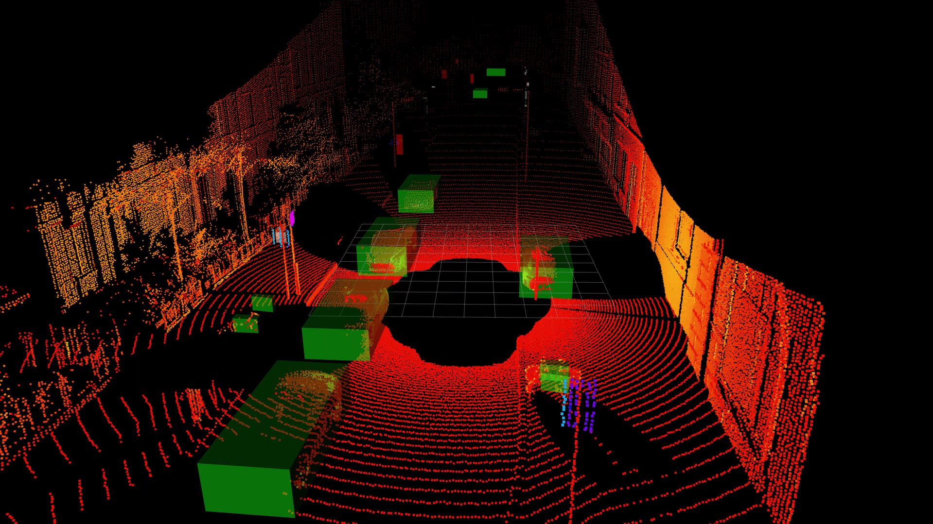
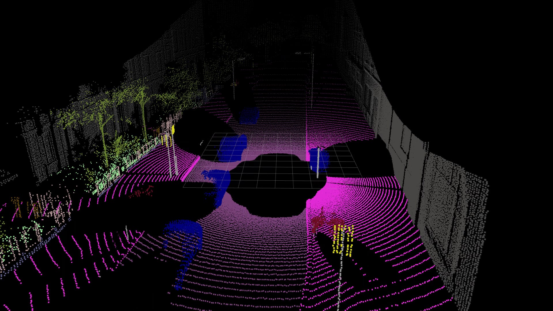
- Output Data: Raw point cloud with intensity/noise, semantic segmentation point cloud, and 3D bounding boxes of detected objects; supported for display on the SimOne platform (including comparison with camera simulation data).
The figure below shows LiDAR output visualized in a ROS system: point-cloud 3D bounding boxes (left) and semantic segmentation data (right).