Dynamics Simulation Parameters
SimOne provides its own proprietary dynamics simulation module and also supports integration with multiple third-party dynamics models including CarSim. Users can configure the desired model as needed by selecting the appropriate dynamics simulation model from the ego vehicle resource library and dragging it into the Ego Vehicle Editor viewport. A single ego vehicle supports only one dynamics simulation model.
SimOne Dynamics Simulation Module
The proprietary SimOne dynamics simulation module receives control signals, drives vehicle motion, and outputs vehicle pose, meeting the dynamics accuracy requirements of autonomous driving algorithm testing. The SimOne dynamics module covers body, control, engine, differential, drivetrain, suspension, tire, and wheel sub-modules, with hundreds of parameters and curves. Detailed parameters, default values, units, and descriptions are provided in the tables below.
1. Body Parameters
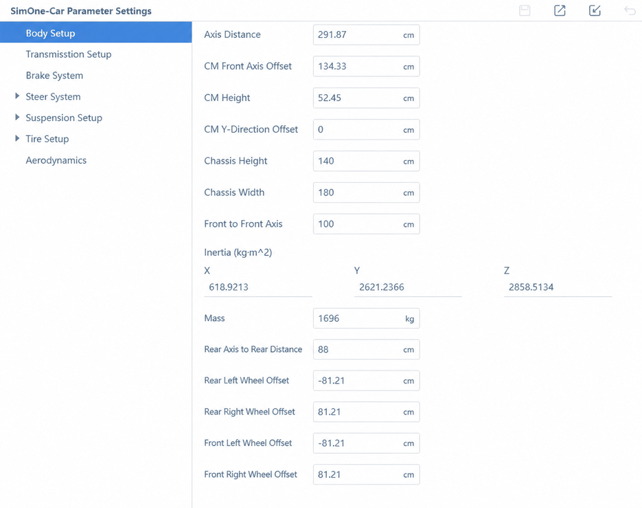
- Wheelbase: Distance between the centerlines of the front and rear axles.
- CG Offset from Front Axle: Distance from the center of gravity (CG) to the front axle centerline.
- CG Height: Distance from the CG to the ground.
- CG Lateral Offset (Y): Lateral distance between the CG and the vehicle's geometric center (uneven interior loading may cause an offset).
- Chassis Height: Vertical distance from the ground to the highest point of the roof.
- Chassis Width: Distance between the widest points on the left and right sides of the body.
- Drag Coefficient: Parameter used to calculate aerodynamic drag in the X direction of the vehicle coordinate system (drag in other directions is currently not considered).
- Front Overhang: Distance from the frontmost point of the vehicle to the front axle centerline.
- Inertia Tensor: Moment of inertia of the vehicle body about its coordinate axes.
- Mass: Total vehicle mass.
- Rear Overhang: Distance from the rearmost point of the vehicle to the rear axle centerline.
- Wheel Offset: Distance from the wheel center plane to the vehicle's geometric center (Y-direction offset).
2. Drivetrain
The drivetrain is divided into two types: Combustion (Fuel) and Electric.
The drivetrain includes the Engine (Motor), Torque Converter, Gearbox, and Differential.
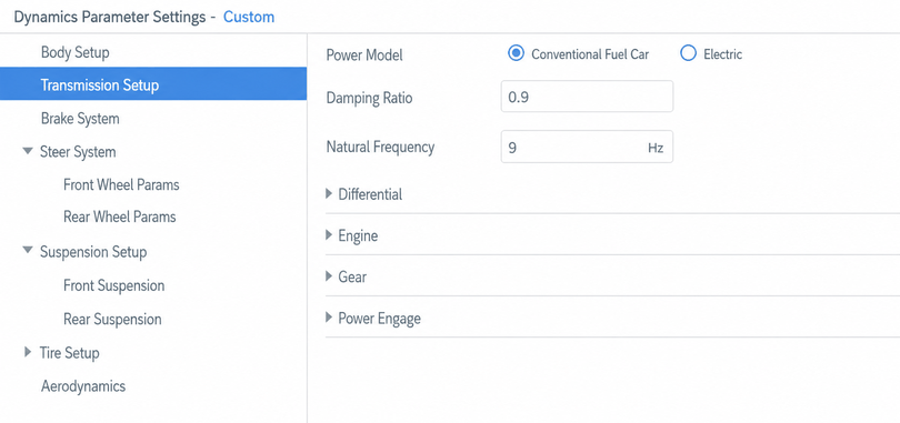
The drivetrain shaft has a certain torsional elasticity. SimOneVehicle uses a torsional spring-damper to simulate this torsional compliance.
2.1 Fuel Vehicle Model
Parameter descriptions:
- Damping Ratio: Drivetrain damping ratio.
- Natural Frequency: Drivetrain natural frequency.
2.1.1 Differential
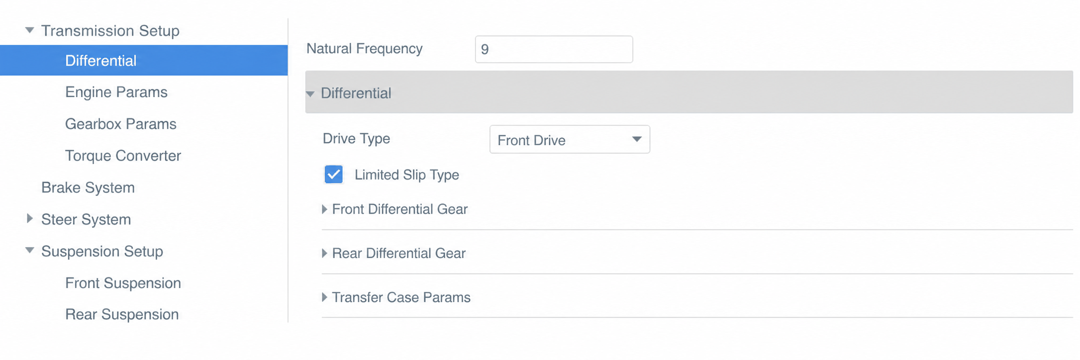
Parameter descriptions:
- Drive Type: Sets the vehicle's drive configuration: front-wheel drive (FWD), rear-wheel drive (RWD), or all-wheel drive (AWD).
- Limited Slip Differential: Check to enable limited-slip functionality.
- Differential parameters:
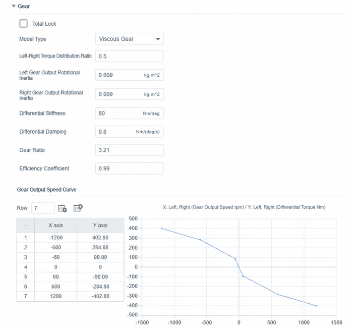
The figure above shows the front differential parameters; the rear differential and transfer case parameters have the same meaning.
Always Locked: When checked, the differential function between the left and right wheels is disabled.
Model Type: Viscous Gear corresponds to a viscous-coupling limited-slip differential.
Torque Bias to Left Wheel: The proportion of differential torque distributed to the left wheel when left and right wheel speeds are equal.
Left Output Shaft Inertia: Moment of inertia of the differential's left output shaft.
Right Output Shaft Inertia: Moment of inertia of the differential's right output shaft.
Torsional Stiffness: Torsional stiffness when the differential is locked.
Torsional Damping: Torsional damping when the differential is locked.
2.1.2 Engine
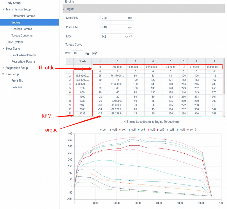
Parameter descriptions:
- Maximum RPM: Maximum engine speed, unit: r/min.
- Idle RPM: Engine speed at idle, unit: r/min.
- Moment of Inertia: Moment of inertia of the engine output shaft, unit: kg*m^2.
- Torque Curve: Engine output torque depends on engine speed and throttle. X-axis: engine speed (r/min). Y-axis: engine torque (Nm). The bottom curve in the chart represents the torque curve at 0 throttle.
2.1.3 Gearbox
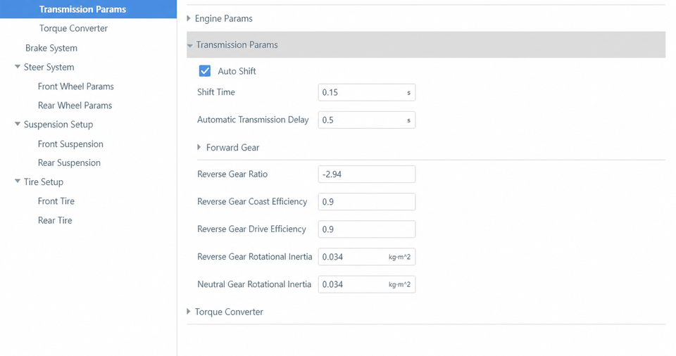
Parameter descriptions:
- Automatic Transmission: Check this box to enable automatic shifting mode.
- Shift Time: Time interval between gear shifts, unit: seconds.
- Automatic Transmission Delay: Response delay, unit: seconds.
- Reverse Gear Ratio: Transmission ratio in reverse.
- Reverse Inertia Coasting Efficiency: Gearbox efficiency when the engine provides braking force in reverse.
- Reverse Drive Efficiency: Gearbox efficiency when the engine drives the vehicle in reverse.
- Forward Gears:
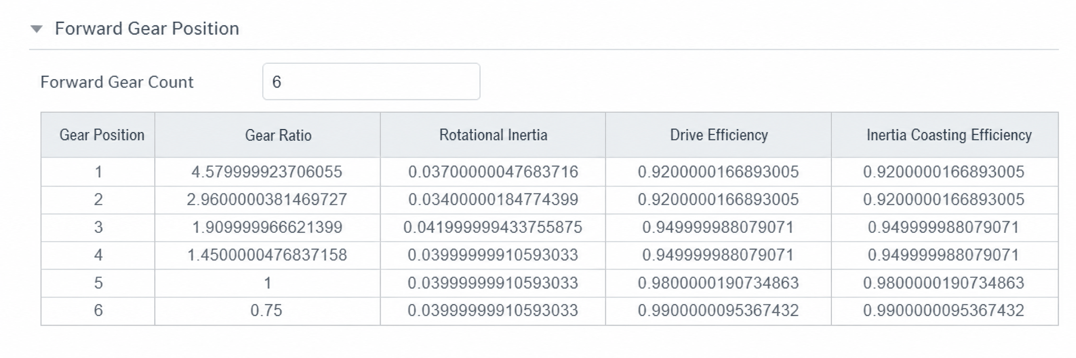
Number of Forward Gears: Highest forward gear.
Gear Ratio: Gearbox transmission ratio at each gear.
Moment of Inertia: Gearbox inertia at each gear.
Drive Efficiency: Gearbox efficiency when the engine drives the vehicle forward.
Inertia Coasting Efficiency: Gearbox efficiency when the engine brakes the forward-moving vehicle.
- Forward Gear Shift Strategy:
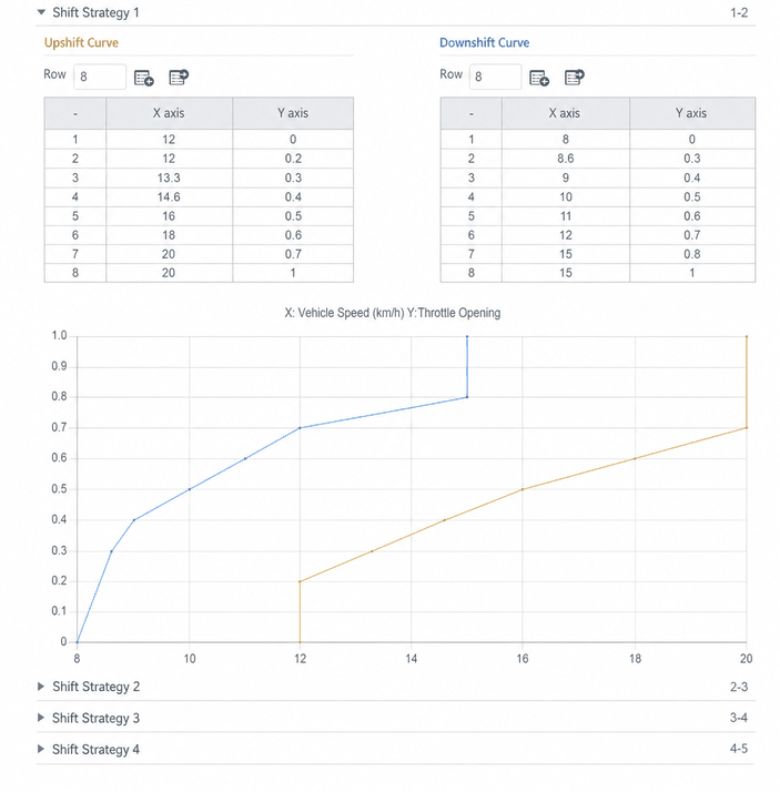
The table above defines the gear-shift conditions between 1st and 2nd gear.
The blue curve is the downshift curve — a downshift occurs when the vehicle state crosses from the right to the left of this curve.
The orange curve is the upshift curve — an upshift occurs when the vehicle state crosses from the left to the right of this curve.
- Torque Converter Lock-Up and Unlock Strategy:
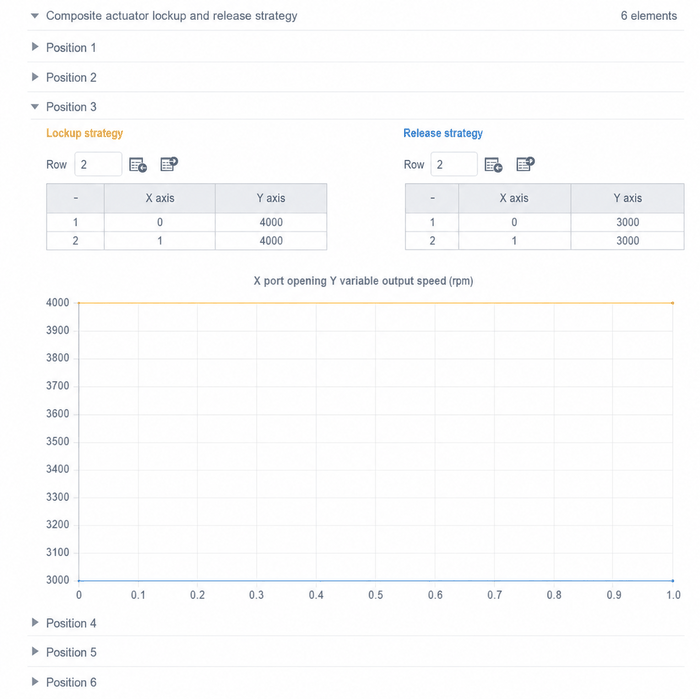
The table above defines the torque converter lock-up and unlock conditions when the gearbox is in 3rd gear.
The orange curve is the lock-up curve — lock-up occurs when the vehicle state crosses from below to above this curve.
The blue curve is the unlock curve — unlock occurs when the vehicle state crosses from above to below this curve.
2.1.4 Torque Converter
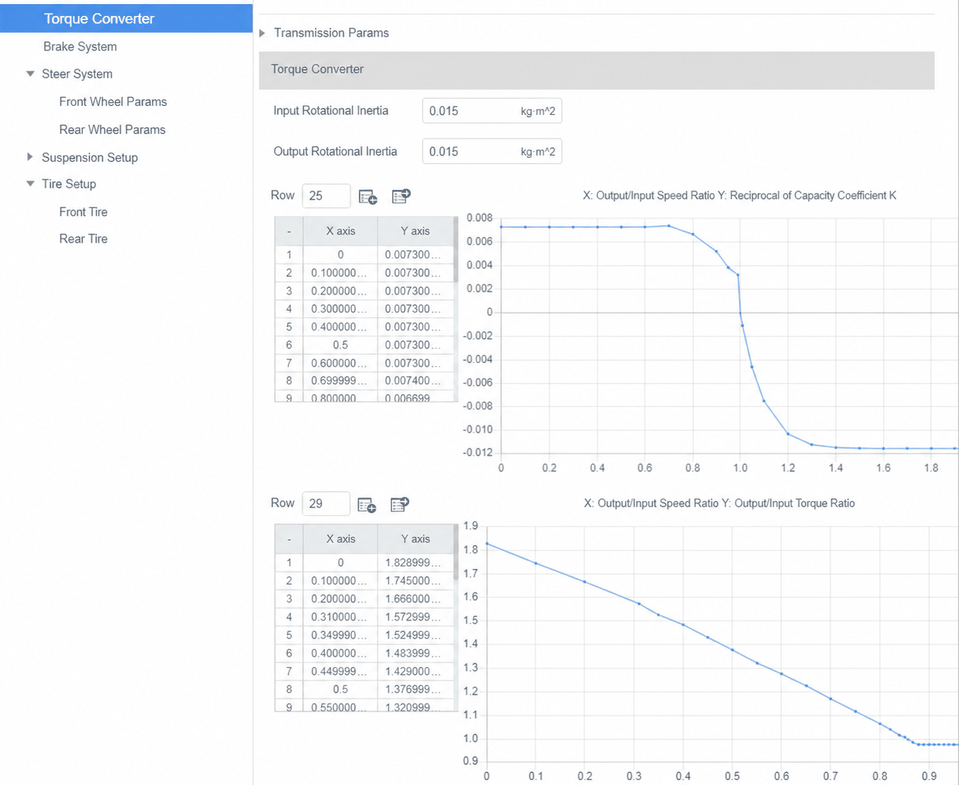
Parameter descriptions:
- Input Inertia: Moment of inertia of the torque converter input shaft, unit: kg*m^2.
- Output Inertia: Moment of inertia of the torque converter output shaft, unit: kg*m^2.
- Capacity Factor vs. Speed Ratio Curve: X-axis: ratio of output shaft speed to input shaft speed. Y-axis: reciprocal of the torque converter's capacity factor.
- Torque Ratio vs. Speed Ratio Curve: X-axis: ratio of output shaft speed to input shaft speed. Y-axis: ratio of output shaft torque to input shaft torque.
2.2 Electric Vehicle Model
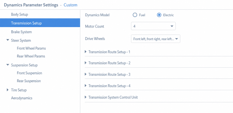
Parameter descriptions:
- Number of Motors: Number of drive motors.
- Drive Wheels: Location of the driven wheels.
- Drivetrain Routing: Set using indices −1/−2/−3/−4 for front-left, front-right, rear-left, and rear-right wheels respectively to define the power transfer path.
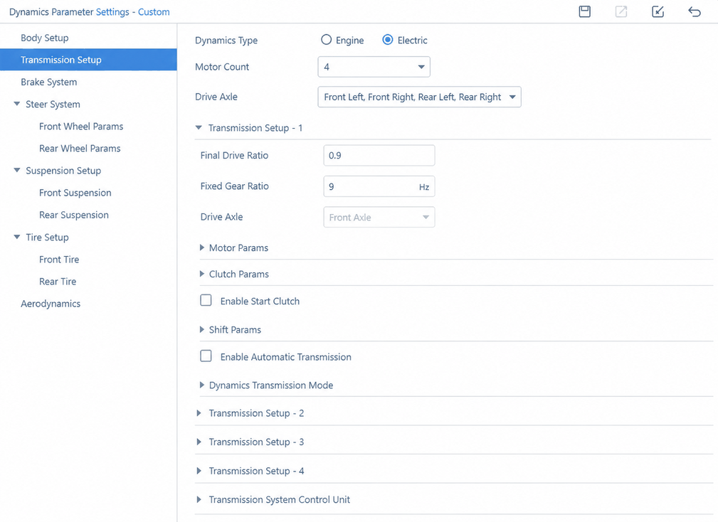 4. Motor Parameters include Moment of Inertia, Speed Limits (upper and lower), Delay Duration, and Torque Characteristics (motor speed vs. motor torque ratio).
-
Differential and Gearbox parameter configurations and meanings are the same as for the fuel vehicle model (see Differential and Gearbox).
-
Power Coupling Type: Clutch or torque converter. Includes input/output inertia, engagement speed, and maximum transferable torque.
-
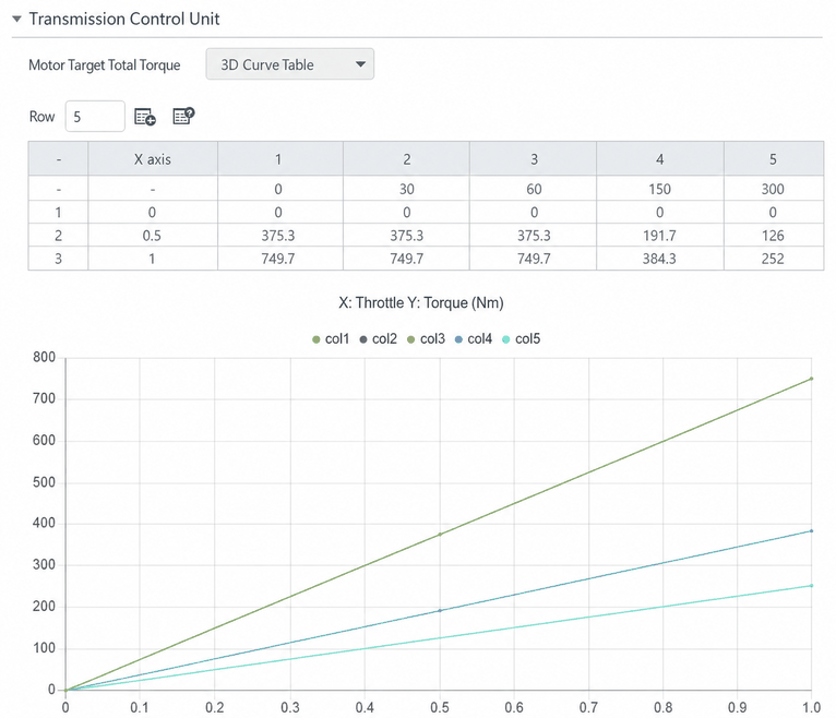
Drivetrain Control Unit: The target total motor torque can be entered as either a 2D or 3D curve table. In the 3D curve, the target torque is vehicle-speed-dependent, adding a vehicle speed dimension compared to the 2D curve.
3. Braking System
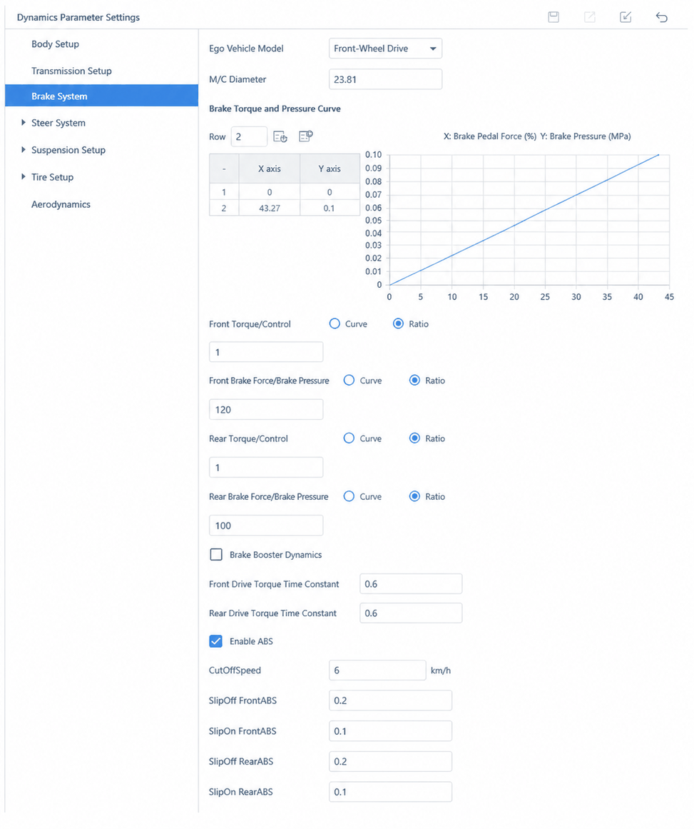
Brake Model: Options include Master Cylinder Control, Pedal Force Control, Pedal Force + Booster Control, and Maximum Brake Torque Control.
3.1 Master Cylinder Control Mode
Parameter descriptions:
- M/C Diameter: Master cylinder bore diameter.
- Brake Opening vs. M/C Pressure Curve: Proportional coefficient (curve) between master cylinder pressure and brake pedal travel.
- Front / Rear Transmission: Front and rear wheel pressure transmission ratio (curve or scalar).
- Front / Rear Brake Torque / Wheel Cylinder Pressure: Proportional coefficient (curve or scalar) between front/rear brake torque and wheel cylinder pressure.
- Brake Dynamics: Caliper flow vs. pressure curve input for front-left, front-right, rear-left, and rear-right wheels.
- Front / Rear Brake Actuator Time Constant: Time constants for front and rear brake actuation.
3.2 Pedal Force Control Mode
- Other parameters are the same as Master Cylinder Control mode.
- Pedal Lever Ratio: Pedal lever ratio; mechanically amplifies the pedal input force.
- Pedal Force Delay: Delay caused by damping and friction in the mechanical system.
3.3 Pedal Force + Booster Control Mode
- Other parameters are the same as Pedal Force Control mode.
- Input Force / Output Force: (Pedal Force + Booster Control) Brake boost curve; amplifies the input force.
3.4 Maximum Brake Torque Control Mode
- No parameters; braking torque is calculated using a linear proportional method.
ABS Parameter Descriptions:
- Enable ABS: Check to activate the ABS system.
- SlipOFF FrontABS: When any front wheel's slip ratio falls below this value multiplied by −1.0, ABS releases braking on that wheel to prevent lock-up.
- SlipON FrontABS: After ABS releases braking and the wheel's slip ratio gradually increases, braking resumes when the ratio exceeds this value multiplied by −1.0.
- SlipOFF RearABS: When any rear wheel's slip ratio falls below this value multiplied by −1.0, ABS releases braking on that wheel to prevent lock-up.
- SlipON RearABS: After ABS releases braking and the rear wheel's slip ratio gradually increases, braking resumes when the ratio exceeds this value multiplied by −1.0.
- Cut-off Speed: Below this vehicle speed, ABS is inactive, unit: km/h.
4. Steering System
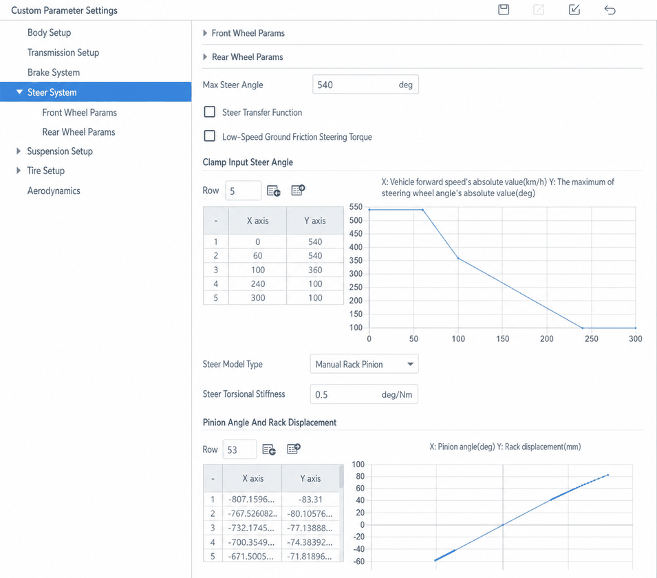
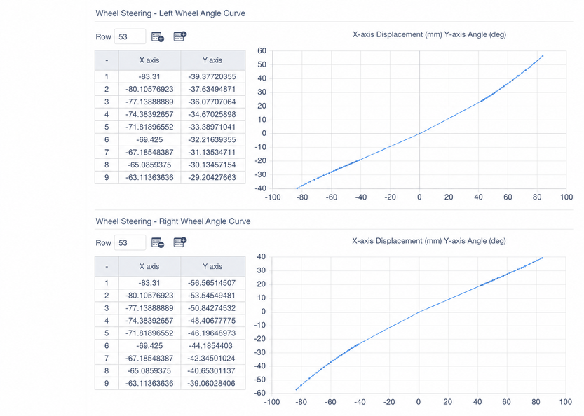
The steering system currently supports only rack-and-pinion front-wheel steering, with steering system elasticity taken into account. The relationship between steering wheel angle and left/right wheel angles is obtained via a lookup table. Rack displacement is derived from the steering pinion angle, and the left/right wheel steering angles are then obtained from the rack displacement.
(1) Steering Stiffness Coefficient: Due to the presence of elastic elements in the steering system, the wheels generate an additional steering angle under the restoring moment.
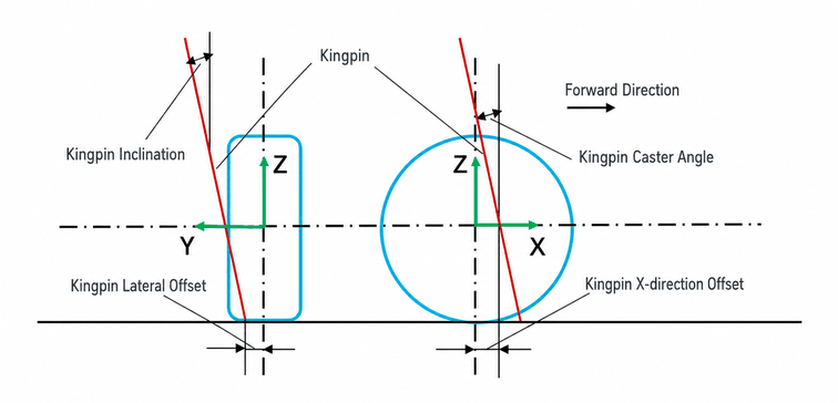
(2) Kingpin Alignment Parameters can be set independently for left and right wheels. The kingpin parameters are defined as shown in the figure below.
(3) Maximum Steering Wheel Angle: When the steering input ranges from −1 to 1, the steering wheel angle corresponds to the negative maximum to the positive maximum. At high speeds, the steering wheel angle should not be too large, but keyboard steering input can easily reach the maximum angle, which is unrealistic. Therefore, the maximum steering wheel angle is limited — the higher the speed, the smaller the allowed maximum steering wheel angle.

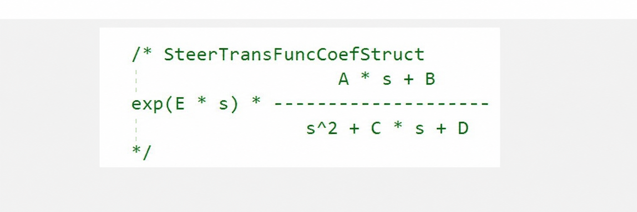
(4) Steering Transfer Function: A transfer function is applied to simulate the actual steering response time of the steering wheel. The polynomial fitting parameters of the transfer function correspond to the Steering Transfer Function Parameters shown in the figure below.
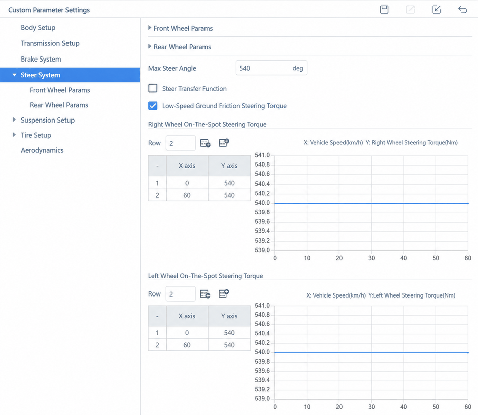
(5) Low-Speed Ground Friction Steering Torque: Tire steering torque at low speed.
- Right / Left Wheel In-Place Steering Torque: Tire torque vs. vehicle speed ratio (table).
Steering Model: Currently supports Rack-and-Pinion and Recirculating Ball models.
4.1 Rack-and-Pinion Model
Parameter descriptions:
- Steering Torsional Stiffness: The steering column, torsion bar in the power-assist system, etc. undergo torsional deformation under torque. This parameter accounts for the effect of such torsional deformation.
4.2 Recirculating Ball Model
Parameter descriptions:
- Steering Wheel to Pitman Arm Ratio: Transmission ratio between the steering wheel and the pitman arm.
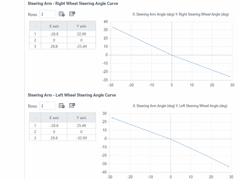
- Pitman Arm to Left/Right Wheel Angle Curve: Proportional relationship (input as a curve) between the pitman arm and the left/right wheel steering angles.
5. Suspension
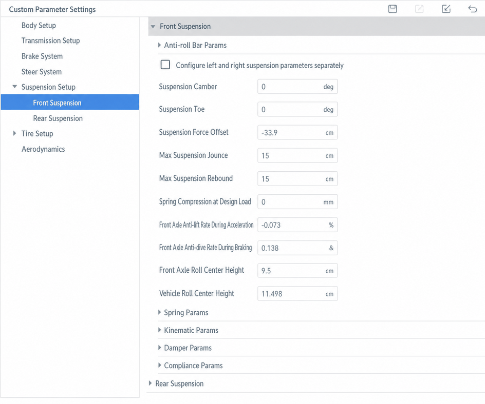
The front suspension includes a spring, anti-roll bar, damper, and accounts for effects such as kinematics and compliance (K&C) characteristics.
(1) Anti-roll bar stiffness can be configured as a lookup table or by natural frequency.
(2) Suspension Camber Angle: Angle between the wheel plane and the longitudinal vertical plane due to the spatial orientation of the suspension.
(3) Suspension Toe Angle: Angle between the vehicle's forward direction and the front wheel plane.
(4) Suspension Force Offset: Distance from the ground force application point to the wheel center; default is negative tire radius (force applied at the ground surface).
(5) Maximum Suspension Droop: Maximum spring extension.
(6) Maximum Suspension Bump: Maximum spring compression.
(7) Spring Compression at Design Load: Spring compression when the vehicle is stationary; default is 0.
(8) Front Axle Anti-Lift Rate Under Acceleration: Front axle anti-lift rate during acceleration.
(9) Front Axle Anti-Dive Rate Under Braking: Front axle anti-dive rate during braking.
(10) Front / Rear Roll Center Height: Roll center height of the front and rear axles.
(11) Vehicle Roll Center Height: Overall vehicle roll center height.
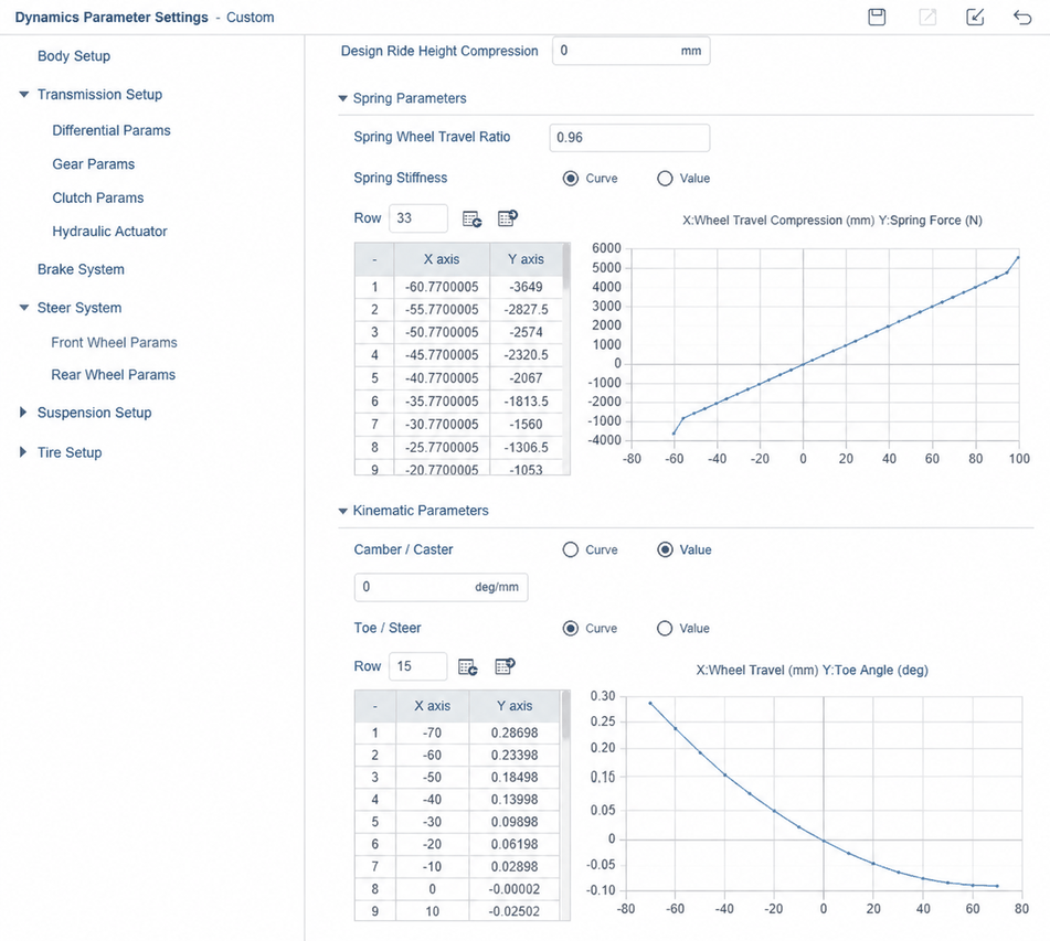
(12) Spring-to-Wheel Travel Ratio: Ratio of spring displacement to wheel travel.
(13) Spring Rate: Can be configured as a curve or constant. Spring compression is positive; extension is negative.
(14) Relationships between camber angle, toe angle, and wheel travel can be configured as constants or curves.
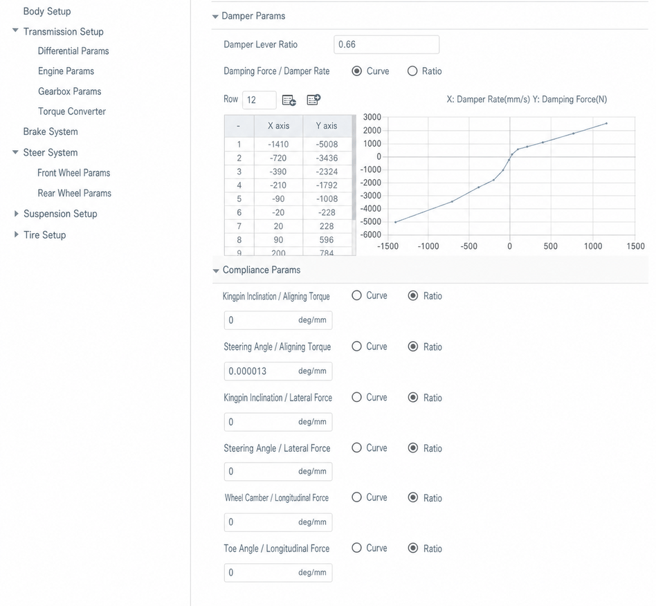
(15) Damper Lever Ratio: Ratio of damper displacement to wheel travel.
(16) Damper Rate can be configured as a constant or a curve.
(17) Compliance parameters can be configured as curves or scalars.
6. Tire
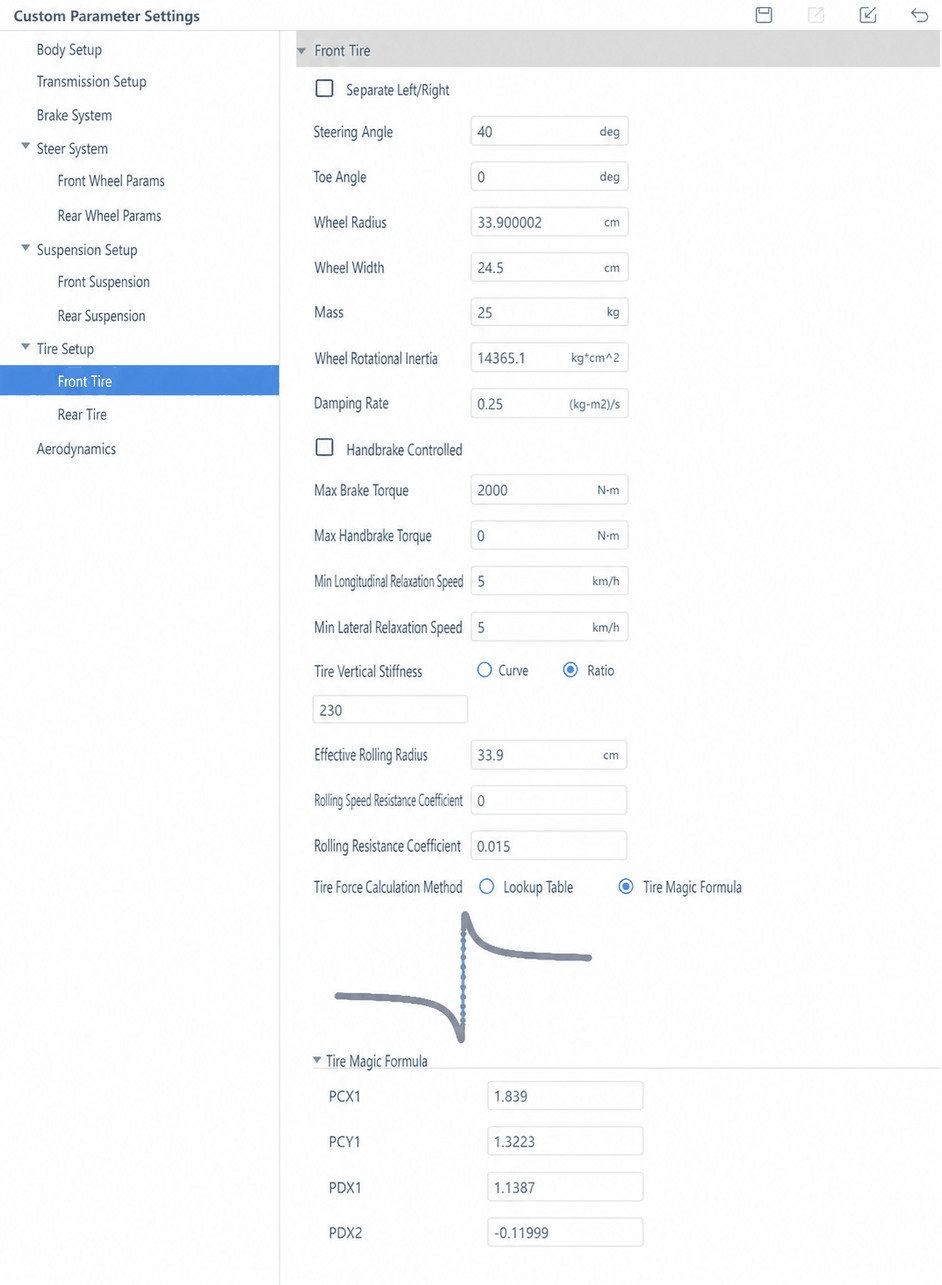
Tire force and moment calculations use the Magic Formula.
- Steering Angle: Maximum wheel steering angle.
- Toe Angle: Default wheel toe angle; inward toe is positive.
- Tire Radius: Tire radius under load.
- Tire Width: Width of the tire tread.
- Mass: Wheel mass.
- Damping Rate: Damping on wheel rotation.
- Maximum Brake Torque: Maximum brake torque multiplied by brake input (0 to 1) to obtain wheel braking torque.
- Maximum Handbrake Torque: Handbrake torque of the tire.
- Minimum Longitudinal Relaxation Speed: Minimum speed for tire longitudinal relaxation.
- Minimum Lateral Relaxation Speed: Minimum speed for tire lateral relaxation.
- Effective Rolling Radius: Rolling radius of a single wheel tire, used to calculate tire linear speed.
- Rolling Speed Resistance Coefficient: Resistance coefficient of the tire during rolling.
- Tire Vertical Stiffness: Force per unit displacement of the tire in the Z direction.
- Rolling Resistance Coefficient: Rolling resistance coefficient multiplied by tire load gives the rolling resistance from the ground.
- Tire Force Calculation Method: Two options — lookup table or Magic Formula.
6.1 Tire Force Calculation Method
- Magic Formula: When the Magic Formula method is selected, the corresponding Magic Formula parameter list is displayed.
- Lookup Table: When the lookup table method is selected, the parameters are as described below.
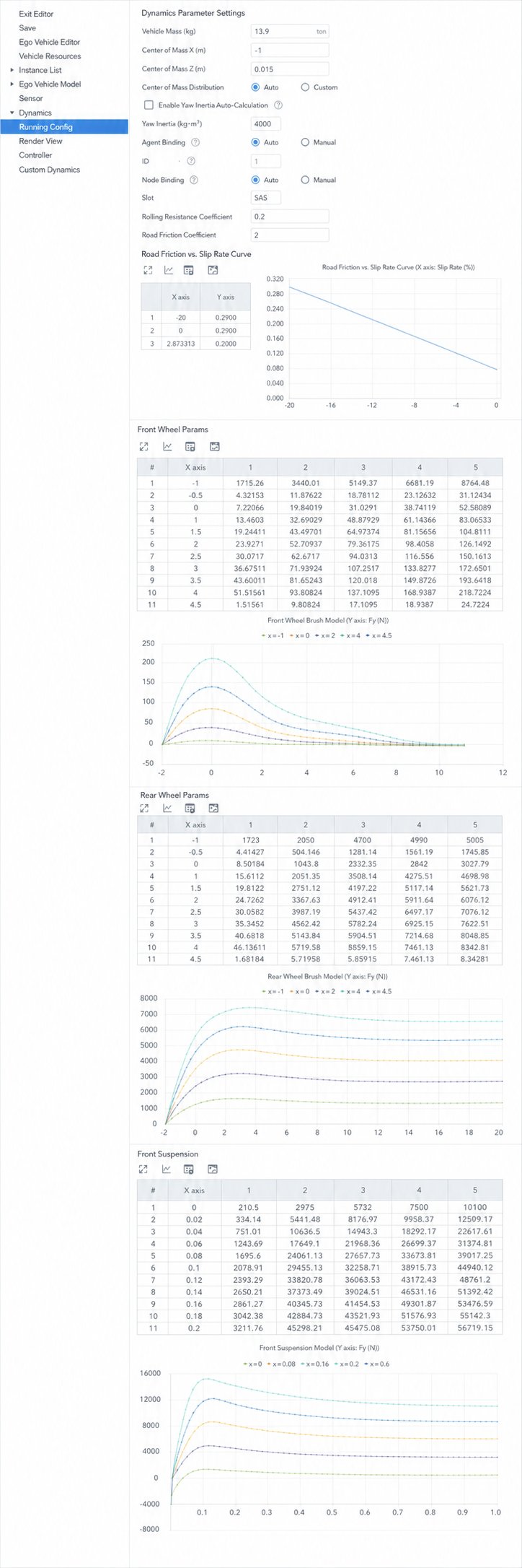
Lookup Table Parameter Descriptions:
- Use Additional Rolling Resistance Effect from Fx: Choose whether to apply this effect.
- Reference Vertical Load: The vertical load used during tire testing.
- Longitudinal / Lateral Relaxation Length: Tire longitudinal/lateral relaxation length (curve or scalar). When a curve is selected, the longitudinal table includes relaxation length vs. vertical load ratio and relaxation length vs. slip ratio; the lateral table includes relaxation length vs. vertical load ratio and relaxation length vs. slip angle.
- Longitudinal / Lateral Relaxation Length Scale Constant: Scale constant for the tire longitudinal/lateral relaxation length.
- Camber Thrust vs. Vertical Load Curve: Camber thrust vs. vertical load curve.
- Aligning Torque Calculation: Data table for computing tire aligning torque.
- Lateral Force Calculation: Data table for computing tire lateral force.
- Longitudinal Force Calculation: Data table for computing tire longitudinal force.
7. Aerodynamics
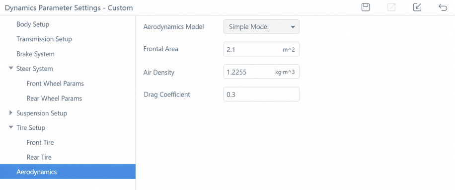
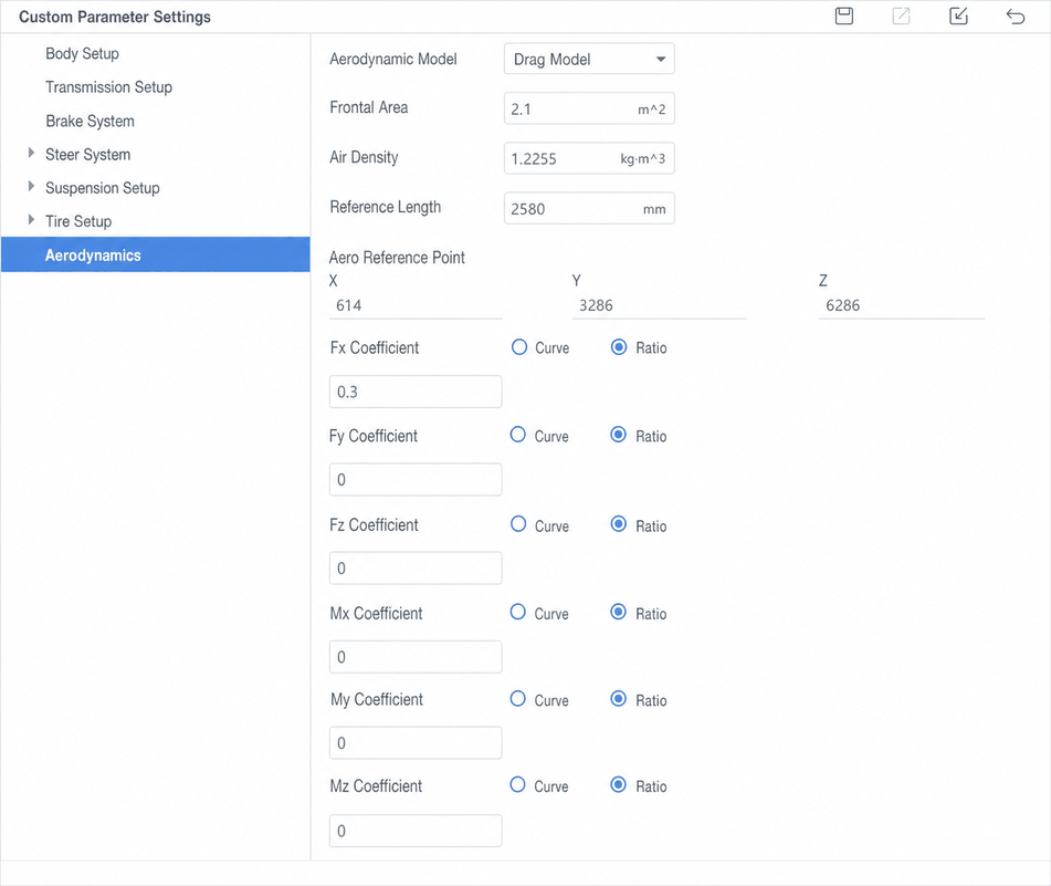
The aerodynamics model is divided into two types: Simple Model and Drag Model.
Parameter descriptions:
- Frontal Area: Frontal area of the vehicle during driving.
- Air Density: Air density around the vehicle during driving.
- Drag Coefficient: (Simple Model) Vehicle aerodynamic drag coefficient.
7.1 Simple Model
7.2 Drag Model
Parameter descriptions:
- Reference Length: Aerodynamic reference length.
- Aerodynamic Reference Point: Coordinates on the vehicle body where the aerodynamic forces act.
- Fx / Fy / Fz Coefficients: Aerodynamic drag angle vs. drag ratio coefficients in the X/Y/Z directions.
- Mx / My / Mz Coefficients: Aerodynamic drag angle vs. drag moment ratio coefficients in the X/Y/Z directions.