Millimeter-Wave Radar Details
1. Overview
The mmWave radar simulation module accurately models the physical propagation mechanism of millimeter-wave signals:
- High-Frequency EM Propagation: Millimeter-wave signals propagate in straight lines at high frequency, with reflections and refraction at object surfaces.
- Range Measurement: Calculates target range by measuring the round-trip time of the signal.
- Velocity Measurement: Detects target velocity using the Doppler effect (frequency shift caused by target motion relative to the radar).
- Angle Measurement: Estimates the azimuth and elevation of targets through spatial comparisons of signals received by multiple antennas.
Two sensor types are supported:
- Standard mmWave Radar: Uses electromagnetic ray-tracing to simulate millimeter-wave signal propagation. Supports accurate measurement of target distance, velocity, and angle, making it suitable for highway driving assistance (ADAS) and obstacle avoidance scenarios.
- 4D mmWave Radar: In addition to standard mmWave capabilities (distance, velocity, azimuth), the 4D radar also simulates elevation measurement to output a high-resolution 4D point cloud (X, Y, Z + velocity), enabling simultaneous detection of height information.
2. Appendix: Simulation Parameter Reference
2.1 Standard mmWave Radar Input Parameters
2.1.1 Basic Information
| No. | Parameter | Definition |
|---|---|---|
| 1 | Frequency | Number of radar scans per second (update rate). For example, 10 Hz means 10 data frames per second. |
| 2 | Horizontal FOV | Horizontal field-of-view angle, defining the range of azimuth detection. |
| 3 | Vertical FOV | Vertical field-of-view angle, defining the range of elevation detection. |
| 4 | Maximum Range | Maximum detection distance; targets beyond this range are not detected. |
| 5 | Minimum Range | Minimum detection distance; targets within this distance may be missed. |
| 6 | Range Resolution | Minimum range interval between two distinguishable targets in the range direction. |
| 7 | Maximum Velocity | Maximum detectable target radial velocity. |
| 8 | Minimum Velocity | Minimum detectable target radial velocity. |
| 9 | Velocity Resolution | Minimum velocity difference for distinguishing two targets in the velocity dimension. |
| 10 | Horizontal Angle Resolution | Minimum angular separation for distinguishing two targets in the horizontal plane. |
| 11 | Vertical Angle Resolution | Minimum angular separation for distinguishing two targets in the vertical plane. |
2.1.2 Perception Error
| No. | Parameter | Definition |
|---|---|---|
| 1 | Target Position Error | Deviation between the radar-measured target position and the actual position. |
| 2 | Target Velocity Error | Deviation between the radar-estimated target velocity and the actual velocity. |
| 3 | Target Angle Error | Difference between the radar-identified target direction and the true direction. |
2.2 4D mmWave Radar Input Parameters
The 4D mmWave Radar shares the above basic parameters with the standard radar and additionally includes the following DSP post-processing parameter, which is critical to simulation accuracy:
2.2.1 DSP Post-Processing Parameters
| No. | Parameter | Definition |
|---|---|---|
| 1 | CA-CFAR (Cell Averaging CFAR) Window Size | In CFAR target detection, this is the number of reference cells used to estimate background noise, determining the sensitivity and false-alarm rate of the detector. |
| 2 | CA-CFAR Guard Cells | The number of protection cells adjacent to the target cell, preventing target energy from polluting the noise estimate; avoids false negatives on strong targets. |
| 3 | CA-CFAR Threshold | Detection threshold = background noise estimate × threshold factor. A higher value reduces false alarms but may miss weak targets. |
| 4 | Noise Floor | The basic noise level below which echo signals cannot be distinguished; also known as the noise level or minimum detectable signal. |
| 5 | Range / Velocity Spectrum Resolution | Resolution in the range–velocity spectrum, determining how closely two targets can be separated in both dimensions simultaneously. |
| 6 | Phase Noise | Random phase fluctuations in the radar's local oscillator, causing smearing of targets in the range–velocity spectrum; affects range and velocity measurement accuracy. |
| 7 | Range / Velocity Spectrum Points | Number of FFT points used in range and velocity processing; affects frequency resolution and processing latency. |
| 8 | Reflection Power Threshold | Minimum reflected signal power for a target to be detected; targets below this threshold are filtered. |
| 9 | Antenna Horizontal Spacing | Spacing between receiving antennas in the horizontal direction; determines the baseline for angle estimation and angular resolution. |
| 10 | Antenna Vertical Spacing | Spacing between receiving antennas in the vertical direction (relevant for 4D elevation measurement). |
| 11 | Number of TX Antennas | Number of transmit antennas; determines MIMO array configuration, affecting both angle measurement capability and target separation. |
| 12 | Number of RX Antennas | Number of receive antennas; determines spatial sampling capability, directly influencing angular resolution. |
| 13 | Number of Doppler Bins | Number of frequency bins in the Doppler dimension; affects velocity resolution and unambiguous velocity range. |
| 14 | Range Overlap | Overlap between consecutive radar data frames in the range dimension; can improve target continuity. |
| 15 | Velocity Overlap | Overlap between consecutive frames in the velocity dimension; similar to range overlap, reduces inter-frame fluctuation. |
| 16 | Nearest Target Range | The minimum range to the nearest valid target; replaces the minimum range parameter in standard radar. |
| 17 | Gain at Nearest Target | Signal gain at the minimum detection range, used to calibrate the maximum SNR at the target. |
| 18 | Gain at Maximum Range | Signal gain at the maximum detection range, used to determine the minimum detectable SNR boundary. |
| 19 | Maximum Attenuation | Maximum signal attenuation tolerated before the signal is considered lost; defines the radar's dynamic range. |
2.3 Output Settings
mmWave radar simulation data supports two output destinations: Network (real-time transmission via UDP/TCP) and Dump (recorded to local files).
2.3.1 Output to [Network]
| No. | Parameter | Definition |
|---|---|---|
| 1 | Subscription Channel | Network address and port at which radar data is published, for algorithm modules or external programs to subscribe and receive. |
2.3.2 Output to [Dump]
| No. | Parameter | Description |
|---|---|---|
| 1 | Dump Frequency | Frequency at which simulation data is recorded; e.g., 5 Hz means 5 dumps per second |
| 2 | Dump Time Range | Sets the start and end time for data recording; data is captured only within this time window |
| 3 | Save To | The directory path where the dump file is saved |
3. Appendix: Simulation Principles
3.1 Standard mmWave Radar Simulation Principles
The standard radar simulation uses electromagnetic ray tracing. Based on the configured radar parameters, the simulator emits rays from the radar position according to the beam pattern, computes intersections with objects in the scene, and calculates target attributes (range, velocity, angle, reflectivity) from the intersection results.
Main simulation steps:
- Emit EM Rays: Generate transmit beams based on the configured horizontal/vertical FOV and resolution.
- Scene Intersection: Compute each ray's intersection with 3D scene objects to obtain the scattering point's position.
- Compute Attributes: Calculate target range (round-trip time), radial velocity (Doppler shift), and angle (multi-antenna phase difference) from the intersection points.
- Add Noise: Superimpose the configured perception error (position, velocity, angle) to simulate real measurement uncertainty.
- Output Data: Publish the simulated point-cloud data over the network or write it to a local file.
3.2 4D mmWave Radar Simulation Principles
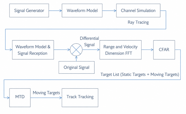
The 4D mmWave radar simulation fully models the physical signal processing chain, covering: RF transmission → echo reception → A/D sampling → digital signal processing → 3D/4D point-cloud output.
The key processing stages are:
- Signal Generation and Transmission: Model the FMCW waveform parameters (chirp rate, bandwidth, carrier frequency) based on configuration, generating the transmitted signal.
- Propagation and Echo: Compute the round-trip time and Doppler shift based on target distance and velocity to simulate the received echo signal.
- Digital Signal Processing (DSP): Process the echo signal using FFT, CFAR detection, and MIMO angle estimation to extract range, velocity, horizontal angle, and elevation:
- Range FFT: Time-to-frequency transform.
- Doppler FFT: Extracts velocity information.
- CFAR detection: Identifies and filters target peaks.
- MIMO angle estimation: Estimates horizontal and vertical angles from multi-antenna signals.
- Point Cloud Generation: Converts detected targets into 4D point clouds (X, Y, Z, velocity) and outputs them.
The figure below shows a 4D mmWave radar scene example:
The ego vehicle is equipped with a 4D mmWave radar. During a drive-by, the radar detects the target vehicle and outputs a 4D point cloud. After applying DSP processing, the target vehicle and other objects in the scene are clearly visible in both the range–velocity and angle dimensions.