Third-Party Middleware: Simulink
SimOne provides Simulink middleware support. Through the SimOneModule block library, SimOne connects the simulation platform to the MATLAB/Simulink environment for co-simulation. Developers can call SimOne sensor data and Ego Vehicle control interfaces directly in Simulink without manually writing C++ bridge code — suitable for control algorithm development and validation scenarios.
1. SimOneModule Overview
1.1 Time Synchronization Module
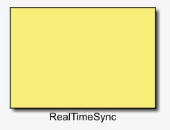
Connects SimOne to Simulink and initializes the SimOneAPI interface. This module is required for co-simulation.
Inputs
None
Parameters
| Parameter | Type | Notes |
|---|---|---|
| IP | int* | A 4-element array; each element corresponds to one octet of the SimOne host IP address |
| FrameSync | int | 0 or 1 — whether to enable frame synchronization. 0 = disabled, 1 = enabled |
Outputs
None
1.2 Ego Vehicle Module
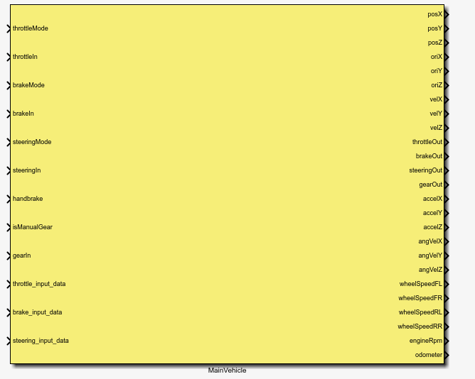
A dynamics-based control mode. Accepts throttle, brake, and steering signals as inputs, and outputs vehicle position, orientation, and other state information.
Inputs
| Parameter | Type | Notes |
|---|---|---|
| throttleMode | enum | Throttle input mode: 0 = percentage, 1 = engine torque, 2 = speed, 3 = acceleration, 4 = engine RPM, 5 = wheel torque. Brake input is ignored in modes 2 and 3. |
| throttleIn | float | Throttle input. Range varies by mode (for reference only): 0 → [0, 1], 1 → Nm, 2 → m/s, 3 → m/s², 4 → rpm, 5 → Nm |
| brakeMode | enum | Brake input mode: 0 = percentage, 1 = master cylinder pressure, 2 = pedal force, 3 = wheel cylinder pressure, 4 = wheel torque |
| brakeIn | float | Brake input. Range varies by mode (for reference only): 0 → [0, 1], 1 → MPa, 2 → N, 3 → MPa, 4 → Nm |
| steeringMode | enum | Steering input mode: 0 = percentage, 1 = angle, 2 = torque, 3 = angular velocity, 4 = tire angle, 5 = tire angular velocity |
| steeringIn | float | Steering input. Negative = left, positive = right. Range varies by mode (for reference only): 0 → [-1, 1], 1 → deg, 2 → Nm, 3 → deg/s, 4 → deg, 5 → deg/s |
| handbrake | bool | Handbrake. Default false (not engaged) |
| isManualGear | bool | Manual transmission. Default false (automatic) |
| gearIn | int | Gear mode input: 0 = neutral, 1 = drive, 2 = reverse |
| throttle_input_data | float* | Input data for throttle mode 5. When used, throttleIn is ignored. |
| brake_input_data | float* | Input data for brake modes 3 and 4. When used, brakeIn is ignored. |
| steering_input_data | float* | Input data for steering modes 4 and 5. When used, steeringIn is ignored. |
Parameters
| Parameter | Type | Notes |
|---|---|---|
| DataSize | int | Data length for throttle_input_data, brake_input_data, and steering_input_data. Default is 0. |
Outputs
| Parameter | Type | Notes |
|---|---|---|
| posXYZ | float | Ego Vehicle position XYZ, unit: m |
| oriXYZ | float | Ego Vehicle rotation XYZ, unit: rad |
| velXYZ | float | Ego Vehicle velocity XYZ, unit: m/s |
| throttleOut | float | Throttle output, percentage mode, [0, 1] |
| brakeOut | float | Brake output, percentage mode, [0, 1] |
| steeringOut | float | Steering output, percentage mode, [-1, 1] |
| gearOut | int | Gear output: -2 = park, -1 = reverse, 0 = neutral, 1/2/... = refer to actual vehicle gears |
| accelXYZ | float | Ego Vehicle acceleration XYZ, unit: m/s² |
| angvelXYZ | float | Ego Vehicle angular velocity XYZ, unit: rad/s |
| wheelSpeed | float* | Ego Vehicle wheel speed: FL (front-left), FR (front-right), RL (rear-left), RR (rear-right), unit: m/s |
| engineRpm | float | Engine RPM |
| odometer | float | Odometer, unit: m |
1.3 Ego Vehicle Module (Position Control)
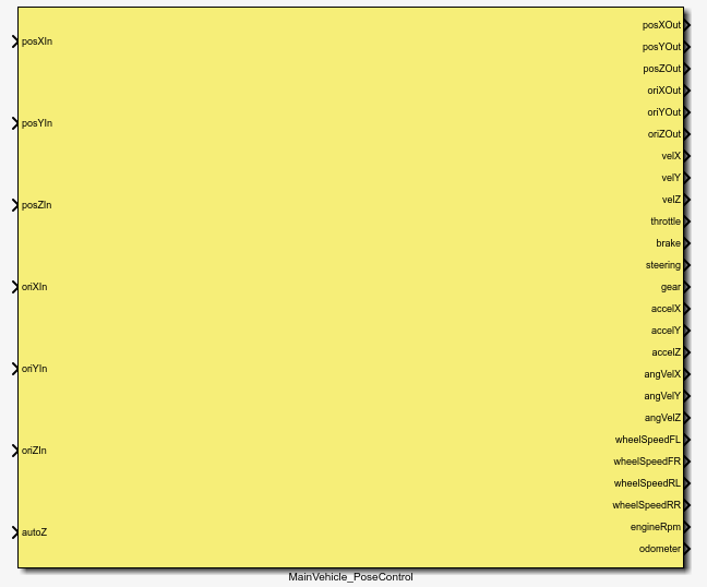
A dynamics-bypass control mode. Directly sets the vehicle's position and orientation, and outputs position, orientation, and other state information.
Inputs
| Parameter | Type | Notes |
|---|---|---|
| posIn | float | Ego Vehicle position XYZ, unit: m |
| oriIn | float | Ego Vehicle rotation XYZ, unit: rad |
| autoZ | bool | Automatically set vehicle height based on the scene. Default false. |
Outputs
Same as the Ego Vehicle Module.
1.4 Driver Module
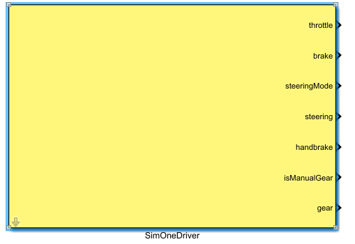
Inputs
None
Parameters
None
Outputs
| Parameter | Type | Notes |
|---|---|---|
| throttle | float | Throttle output, [0, 1] |
| brake | float | Brake output, [0, 1] |
| steeringMode | enum | Steering mode: 0 = percentage, 1 = angle, 2 = torque, 3 = angular velocity, 4 = tire angle, 5 = tire angular velocity |
| steering | float | Steering output. Negative = left, positive = right. [-1, 1] |
| handbrake | bool | Handbrake. Default false (not engaged) |
| isManualGear | bool | Manual transmission. Default false (automatic) |
| gear | int | Gear output: -2 = park, -1 = reverse, 0 = neutral, 1/2/... = refer to actual vehicle gears |
1.5 Obstacle Module (GroundTruth — No Sensor Configuration Required)
Note: Current obstacle detection range is 100 m.
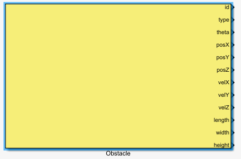
Retrieves ground-truth information for obstacles by reading internal data.
Inputs
None
Parameters
| Parameter | Notes |
|---|---|
| ObstacleNum | Maximum number of obstacles to detect |
| ObstacleId | Obstacle detection ID, starting from 1 |
Outputs
| Parameter | Type | Notes |
|---|---|---|
| id | int | Obstacle ID in SimOne, starting from 11 |
| type | enum | See obstacle type description below |
| theta | float | Obstacle rotation angle around the Z-axis, unit: rad |
| posXYZ | float | Obstacle position XYZ, unit: m |
| velXYZ | float | Obstacle velocity XYZ, unit: m/s |
| length | float | Obstacle bounding box length, unit: m |
| width | float | Obstacle bounding box width, unit: m |
| height | float | Obstacle bounding box height, unit: m |
| accelXYZ | float | Obstacle acceleration XYZ, unit: m/s² |
Obstacle Type Description
enum SimOne_Obstacle_Type {
        ESimOne_Obstacle_Type_Unknown = 0,
        ESimOne_Obstacle_Type_Pedestrian = 4,
        ESimOne_Obstacle_Type_Pole = 5,
        ESimOne_Obstacle_Type_Car = 6,
        ESimOne_Obstacle_Type_Static = 7,
        ESimOne_Obstacle_Type_Bicycle = 8,
        ESimOne_Obstacle_Type_Fence = 9,
        ESimOne_Obstacle_Type_RoadMark = 12,
        ESimOne_Obstacle_Type_TrafficSign = 13,
        ESimOne_Obstacle_Type_TrafficLight = 15,
        ESimOne_Obstacle_Type_Rider = 17,
        ESimOne_Obstacle_Type_Truck = 18,
        ESimOne_Obstacle_Type_Bus = 19,
        ESimOne_Obstacle_Type_SpecialVehicle = 20,
        ESimOne_Obstacle_Type_Motorcycle = 21,
        ESimOne_Obstacle_Type_Dynamic = 22,
        ESimOne_Obstacle_Type_GuardRail = 23,
        ESimOne_Obstacle_Type_SpeedLimitSign = 26,
        ESimOne_Obstacle_Type_BicycleStatic = 27,
  ESimOne_Obstacle_Type_RoadObstacle = 29
};
1.6 Camera Module (Requires Camera Sensor Configuration)
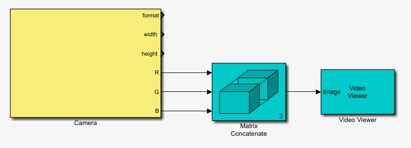
Corresponds to a physical-level camera in SimOne. Retrieves camera data.
Inputs
None
Parameters
| Parameter | Type | Notes |
|---|---|---|
| IP | int* | 4-element array corresponding to the 4 octets of the IP address — must match the sensor settings on the SimOne page |
| Port | int | Port number — must match the sensor settings on the SimOne page |
| CameraId | int | Camera ID assigned to the sensor on the SimOne page (numeric part of the ID) |
| HorizontalResolution | int | Camera horizontal resolution — must match the sensor settings on the SimOne page |
| VerticalResolution | int | Camera vertical resolution — must match the sensor settings on the SimOne page |
Outputs
| Parameter | Type | Notes |
|---|---|---|
| format | int | Image format: 0 = RGB. Currently only RGB is supported. |
| width | int | Image width, per SimOne sensor settings (max 1920) |
| length | int | Image height, per SimOne sensor settings (max 1080) |
| R, G, B | uint8 | Image data. Use VideoViewer to preview camera image data. |
1.7 LiDAR Module (Requires LiDAR Sensor Configuration)
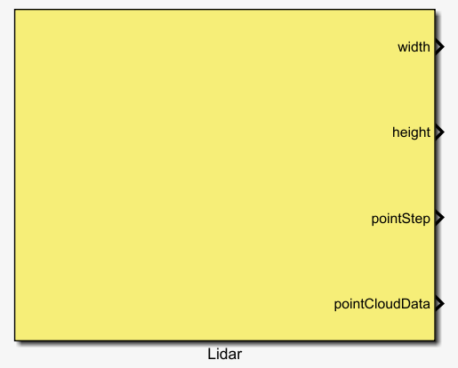
Corresponds to a physical-level LiDAR in SimOne. Retrieves point cloud data.
Inputs
None
Parameters
| Parameter | Type | Notes |
|---|---|---|
| IP | int* | 4-element array corresponding to the 4 octets of the IP address — must match the sensor settings on the SimOne page |
| Port | int* | 2-element array corresponding to 2 port values — must match the sensor settings on the SimOne page |
| LidarId | int | LiDAR ID assigned to the sensor on the SimOne page (numeric part of the ID) |
| PointCloudDataSize | int | Point cloud data size — must match the sensor settings on the SimOne web page |
Outputs
| Parameter | Type | Notes |
|---|---|---|
| width | int | Point cloud image width, per SimOne sensor configuration |
| length | int | Point cloud image length, per SimOne sensor configuration |
| pointStep | int | Bytes per point, per SimOne sensor configuration |
| pointCloudData | uint8* | Point cloud data array (max 3,686,400) |
1.8 Millimeter-Wave Radar Module (Requires Radar Sensor Configuration)
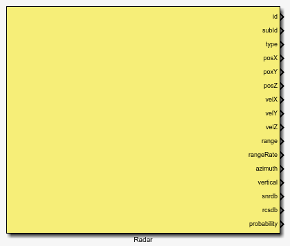
Corresponds to an object-level millimeter-wave radar in SimOne. Retrieves obstacle information within the detection range, and outputs obstacle information corresponding to the specified radar detection index.
Inputs
None
Parameters
| Parameter | Notes |
|---|---|
| RadarId | Millimeter-wave radar ID |
| RadarDetectNum | Maximum number of radar targets to detect |
| RadarDetectionsId | Radar detection target index, starting from 1 |
Outputs
| Parameter | Type | Notes |
|---|---|---|
| id | int | Target ID in SimOne |
| subId | int | Target sub-ID |
| type | int | See obstacle type description in the Obstacle Module |
| posXYZ | float | Target position XYZ, unit: m |
| velXYZ | float | Target velocity XYZ, unit: m/s |
| range | float | Target distance, unit: m |
| rangeRate | float | Target relative velocity, unit: m/s |
| azimuth | float | Target azimuth angle, unit: rad |
| vertical | float | Target elevation angle, unit: rad |
| snrdb | float | Signal-to-noise ratio, unit: dB |
| rcsdb | float | Radar cross-section, unit: dB |
| probability | float | Target detection probability |
1.9 Ultrasonic Radar Module (Requires Ultrasonic Sensor Configuration)
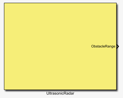
Corresponds to an object-level ultrasonic radar in SimOne. Retrieves information on all obstacles within the detection range.
Inputs
None
Parameters
| Parameter | Type | Notes |
|---|---|---|
| UltrasonicRadarId | int | Ultrasonic radar ID |
| UltrasonicDetectNum | int | Maximum number of ultrasonic detection targets |
Outputs
| Parameter | Type | Notes |
|---|---|---|
| obstacleRanges | float* | Target relative distances, unit: m |
1.10 V2X Module (Requires OBU Sensor Configuration)
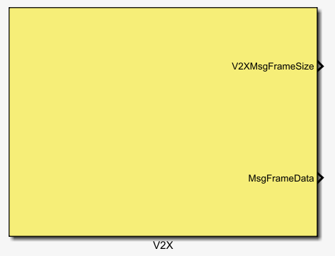
Corresponds to an object-level OBU sensor in SimOne. Retrieves and outputs V2X information.
Inputs
None
Parameters
| Parameter | Type | Notes |
|---|---|---|
| SensorId | int | OBU sensor ID |
| InfoType | enum | V2X information type: 1 = BSM, 2 = MAP, 3 = RSM, 4 = SPAT, 5 = RSI |
| MaxDataSize | int | Maximum V2X message byte count |
Outputs
| Parameter | Type | Notes |
|---|---|---|
| V2XMsgFrameSize | int | Actual V2X message byte count |
| MsgFrameData | int* | V2X message ASCII codes |
1.11 Sensor Configuration Module
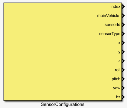
Retrieves information for all sensors, and outputs sensor information corresponding to the specified sensor index.
Inputs
None
Parameters
| Parameter | Type | Notes |
|---|---|---|
| SensorNum | int | Maximum number of sensors |
| SensorConfigId | int | Sensor index, starting from 1 |
Outputs
| Parameter | Type | Notes |
|---|---|---|
| index | int | Overall sensor ID |
| mainVehicle | int | ID of the Ego Vehicle carrying this sensor |
| sensorId | int | Sensor ID (numeric part, as ASCII codes) |
| sensorType | int8* | Sensor type (text part, as ASCII codes) |
| posXYZ | float | Sensor position XYZ, unit: m |
| oriXYZ | float | Sensor rotation XYZ, unit: rad |
| hz | int | Sensor frequency |
1.12 Sensor Detection Module
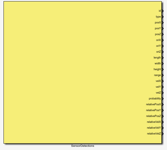
Retrieves detection information from a specified sensor, and outputs obstacle information corresponding to the specified detection target index.
Inputs
None
Parameters
| Parameter | Type | Notes |
|---|---|---|
| SensorId | int | Sensor ID |
| SensorDetectNum | int | Maximum number of sensor detections |
| SensorDetectionsId | int | Sensor detection target index, starting from 1 |
Outputs
| Parameter | Type | Notes |
|---|---|---|
| id | int | Target ID in SimOne, starting from 1 |
| type | int | See obstacle type description in the Obstacle Module |
| posXYZ | float | Target position XYZ, unit: m |
| oriXYZ | float | Target rotation XYZ, unit: rad |
| length | float | Target bounding box length, unit: m |
| width | float | Target bounding box width, unit: m |
| height | float | Target bounding box height, unit: m |
| range | float | Target relative distance, unit: m |
| velXYZ | float | Target velocity XYZ, unit: m/s |
| probability | float | Target detection probability |
| relativePosXYZ | float | Target relative position XYZ, unit: m |
| relativeVelXYZ | float | Target relative velocity XYZ, unit: m/s |
2. HDMapModule Overview
The HDMapModule blocks provide the HD map information needed for co-simulation scenarios.
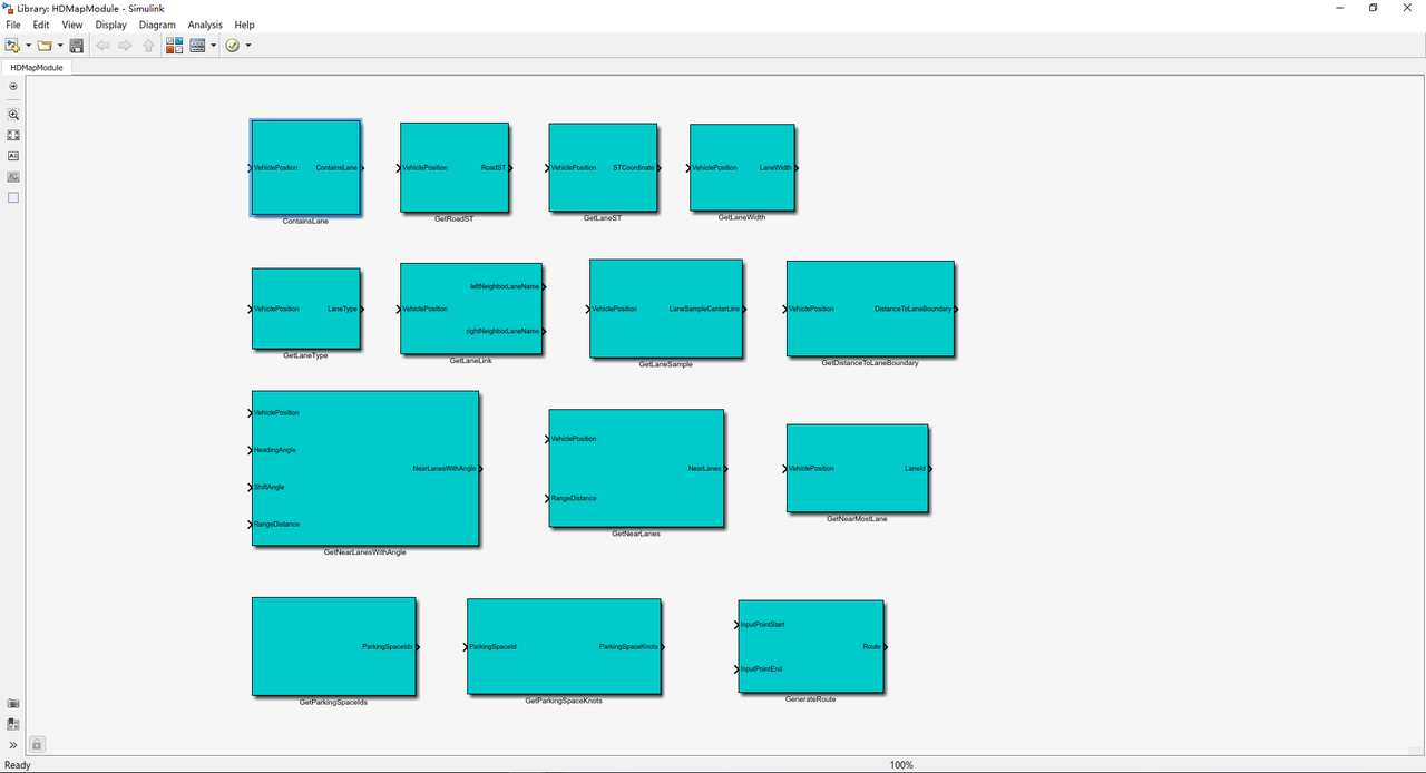
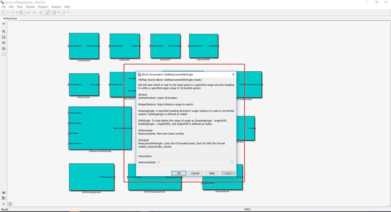
To learn about the function of each block, double-click the block to view its description:
3. Simulink Co-Simulation Code Generation
Building on the existing SimOne–Simulink co-simulation setup, users can generate code from a Simulink co-simulation model, compile it into an executable, and run it locally or in the cloud. (Note: This workflow requires source code. Please contact SimOne customer service or sales for details.)
3.1 Windows
Note: The packaging process below requires Visual Studio or a compatible C/C++ compiler to be installed locally.
Set up the co-simulation environment in MATLAB on Windows, add the relevant blocks from SimOneModule and HDMapModule along with your custom algorithm blocks, and verify that the simulation runs correctly. The following is a simple example:
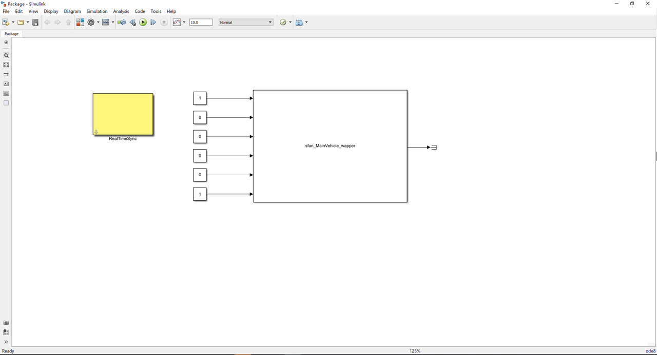
Note
The directory containing the Simulink model file must include the mex files and src files for the corresponding blocks. S-functions with parameters must also include the corresponding Matlabtlc files.
Open Model Configuration Parameters from the Simulation menu.
3.1.1 Configuring Parameters
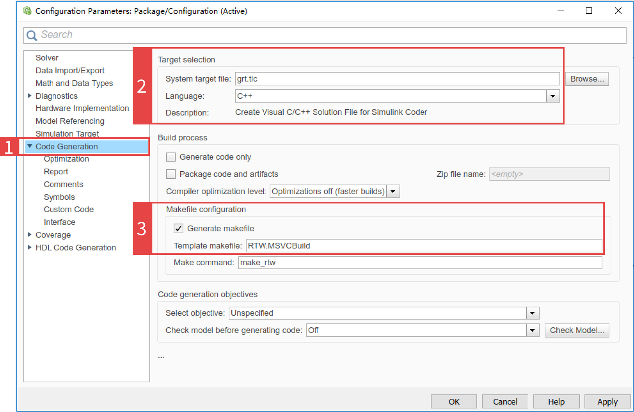
In the Configuration window, select and expand the Code Generation section in the left panel, and apply the following settings:
(1) Select Code Generation itself.
- Under Target selection:
- Set System target file to
grt.tlc (Create Visual C/C++ Solution File for Simulink Coder). - Set Language to
C++. - Check that Template makefile under Makefile configuration is set to
RTW.MSVCBuild.
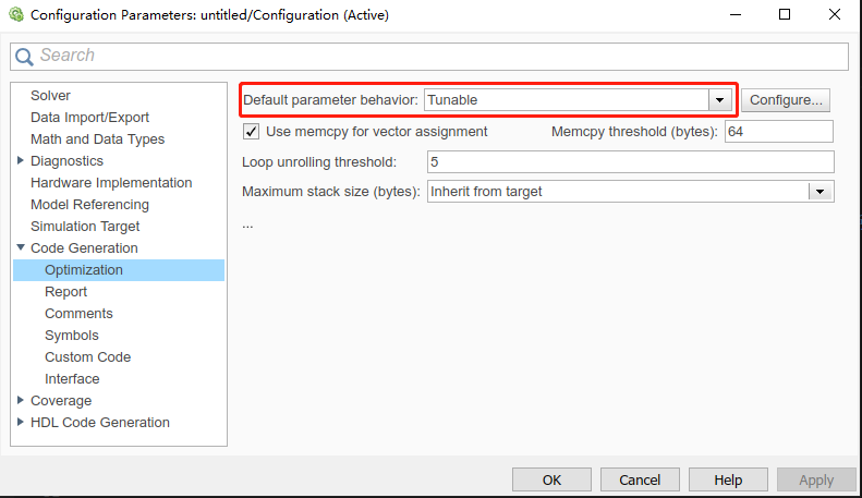
(2) Select the Optimization tab. Set Default parameter behavior to Tunable so that S-function parameters can be adjusted in the Visual Studio project.
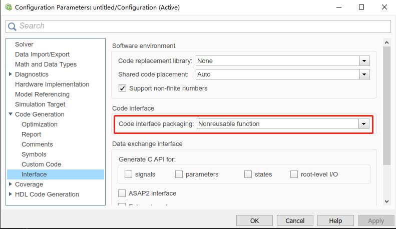
(3) Select Interface under Code Generation. Set Code Interface to Nonreusable function — since the output is a single executable, code reuse is not needed.
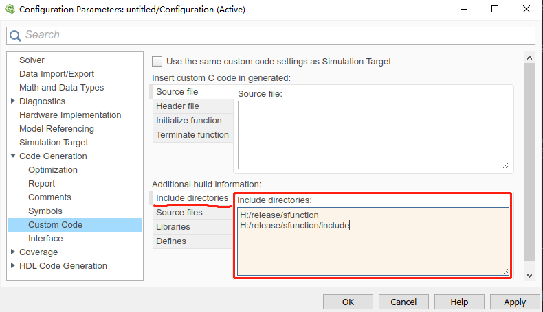
(4) Select Custom Code under Code Generation. In the Include directories field, add the paths to required header files (SimOne's Matlab -> Simulink folder and SDK -> include folder).
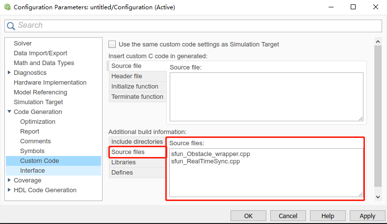
(5) In Source files, enter the source files corresponding to each SimOne S-function block used (the _wrapper.cpp file for each S-function by name).
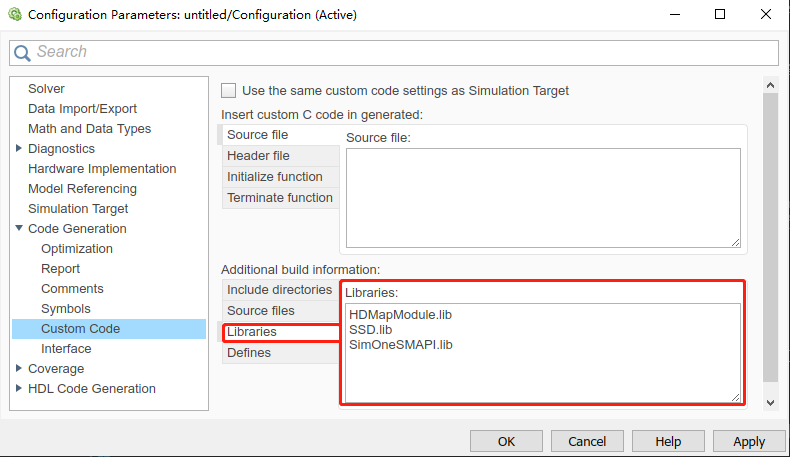
(6) In Libraries, enter the static library files in the Simulink folder (HDMapModule.lib, SSD.lib, and SimOneSMAPI.lib) along with any other project dependencies.
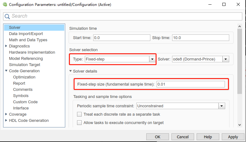
(7) Select the Solver tab. Under Solver Selection, set Type to Fixed-step. The recommended Fixed-step size is 0.01.
3.1.2 Generating a Visual Studio Project
After completing the Simulink Coder configuration, generate the code by selecting Code → C/C++ Code → Build Model, or pressing Ctrl+B.
- Simulink will automatically generate the corresponding Visual Studio project and save it to
Simulink Models/grt_rtw. - If code generation is successful, the generated Visual Studio project will open automatically.
3.1.3 Compiling the Executable in Visual Studio
(1) Adjust Windows SDK Configuration
Configure the appropriate Windows SDK version as needed:

(2) Set Simulation Parameters
In the Simulink project in Visual Studio:
- Use
rtmSetTFinalin the.cppfile with the same name as the Simulink model (.slx) to specify the simulation run time. - Set simulation parameters and control inputs in
<slx_file_name>_data.cpp.
(3) Handle S-Function Outputs
Implement the S-function block in the sfun_<function_name>.cpp file and output the block results.
(4) Running the Executable
To successfully run the packaged executable:
- Ensure all required
.dllfiles are present in the same directory as the executable. These are the dynamic libraries required for co-simulation.
Note
In Model Configuration Parameters → Code Generation → Target selection, you can also select grt.tlc (Generic Real-Time Target). With this option, MATLAB directly invokes the compiler to build the executable in the Simulink Models directory. However, this approach does not allow modification of the simulation time or input/output parameters.
3.2 Linux
Compile the code generated on Windows in a Linux environment.
(1) Copy Source Files:
- Copy the code generated by Simulink on Windows (including
.hheader files and.cppsource files) to the Linux system. - Place the source files in the Matlab path of the SimOne simulation environment — specifically in a custom
grt_rtwfolder.
(2) Modify the Makefile:
- Use the Makefile template provided by SimOne to make the necessary modifications to the original Makefile so it is compatible with the Linux system and build environment.
(3) Build on Linux:
- In the directory containing the source code and modified Makefile, run
maketo compile the code and generate a Linux executable.
(4) Run the Executable:
- To run the compiled executable on Linux, ensure that the required
.soshared library files are present in the same directory as the executable. These libraries provide the dependencies required for co-simulation.
Note
The packaging process above requires MATLAB to be installed locally (the Matlab path in the Makefile must match the installation path), as well as gcc/g++ or a compatible C/C++ compiler.