Configure Sensor Devices
1. Overview
In SimOne, sensors are the core components through which the ego vehicle acquires information about its surroundings. Using the Ego Vehicle Editor, you can flexibly configure multiple sensor types to support a range of use cases — from perception algorithm validation to planning and control testing.
1.1 Supported Sensor Types
The following sensor simulation models are currently supported in SimOne (Collaboration Edition cloud does not support perception sensors):
| Type | Supported Devices | Documentation | Capabilities | Preview |
|---|---|---|---|---|
| Object-Level Sensor | Object-Level Camera, Object-Level LiDAR, Object-Level mmWave Radar, Object-Level Ultrasonic Radar | Object-Level Sensor Details | Directly outputs structured object-list ground truth for rapid planning & control validation | 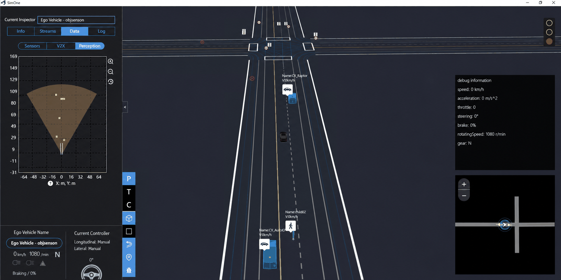 |
| Physical-Level Sensor | Camera, LiDAR, mmWave Radar (Standard / 4D), Ultrasonic Radar | Camera Details LiDAR Details mmWave Radar Details Ultrasonic Radar Details |
Outputs physical-level perception data for perception and fusion algorithm validation | 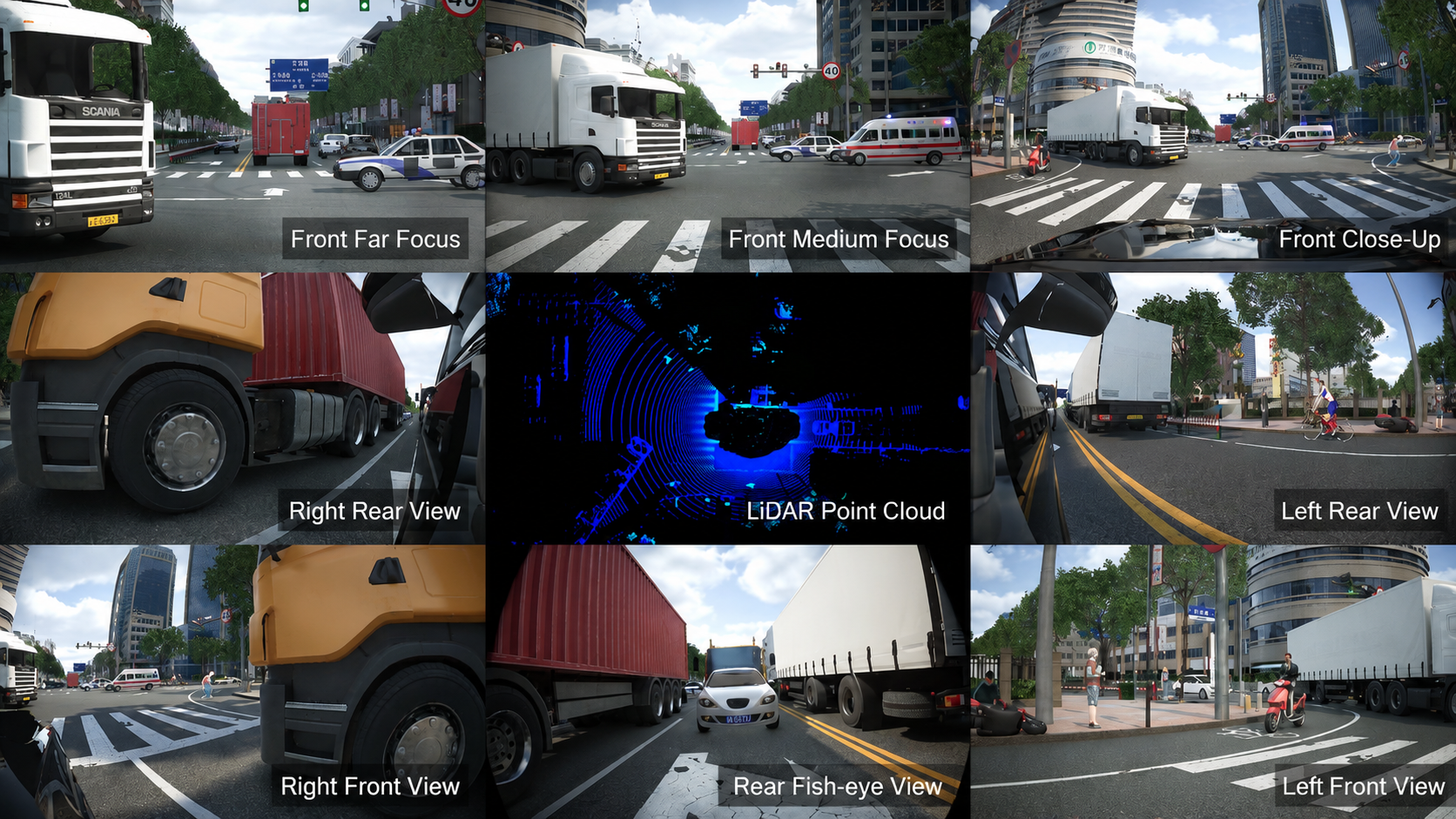 |
| Positioning Sensor | GPS / GNSS / IMU | Positioning Sensor Details | Provides vehicle position, velocity, and attitude information | |
| V2X Communication Device | OBU / RSU | 7.5. V2X Simulation Testing | Provides vehicle-to-everything (V2X) communication capability |
2. General Workflow
2.1 Adding a Sensor
- Locate the desired sensor type in the [Ego Vehicle Resource Library] on the left.
- Hold the left mouse button and drag it into the ego vehicle 3D viewport in the center or into the resource list on the left.
- Release the mouse button — the sensor is now added.
2.2 Adjusting Position and Hierarchy
- Move / Rotate: Modify
X/Y/ZorRoll/Pitch/Yawin the right-side parameter panel. - Create a Fusion Group: Applies to object-level sensors only. Select multiple sensors and click the "+ Fusion Group" button at the top of the list (see Object-Level Sensor Details).
3. Common Parameters and Validation
The following parameters apply to all sensor types.
3.1 Basic Information
| No. | Parameter | Definition |
|---|---|---|
| 1 | Sensor ID | Unique identifier for this sensor instance, used to distinguish between multiple sensors of the same type. |
| 2 | Sensor ClassID | Sensor type, e.g., camera. |
| 3 | Sensor Position X, Y, Z | Defines the sensor's mounting position in the vehicle coordinate system. |
| 4 | Sensor Orientation Roll, Pitch, Yaw |
Defines the sensor's orientation in the vehicle body coordinate system: • Roll: rotation about the X axis • Pitch: rotation about the Y axis • Yaw: rotation about the Z axis |
| 5 | Enabled | Whether this sensor simulation module is active. |
3.2 Output Settings (Physical-Level Only)
Object-level sensors do not have output settings; only physical-level sensors do.
Dump Settings
| No. | Parameter | Definition |
|---|---|---|
| 1 | Dump Frequency | E.g., 5 Hz means 5 dumps per minute |
| 2 | Dump Start / End Time | E.g., start recording at simulation second 10 and stop at second 30 |
| 3 | Save To | Output file save path |
4. Detailed Configuration Guides
Refer to the corresponding parameter reference for your sensor type:
On-Board Sensors
- 🎯 Object-Level & Fusion Sensors 👉 Object-Level & Ideal Sensor Details
-
📸 Physical-Level Sensors 👉
-
🖥️ Distributed Node Configuration 👉 Sensor Distributed Nodes
- 🔧 Sensor Algorithm Debugging 👉 Sensor Algorithm Debugging
- 📊 Synthetic Data for Algorithm Training 👉 Synthetic Data Generation
Roadside Sensors
- Same as Synthetic Data above