Sensor Model Confidence Testing
Sensor model confidence is one of the fundamental prerequisites for L2 admission testing. This section describes the sensor model confidence test methodology: by reproducing a checkerboard calibration experiment in the SimOne dedicated calibration room simulation map, and comparing real captured images against simulation-generated images, the geometric accuracy confidence of the camera sensor is quantified.
1. Real Data Collection
1.1 Calibration Board Types
The checkerboard calibration board type and dimensions used in the test must be aligned with the corresponding assets in SimOne simulation. The pattern must be complete. Two types are currently supported:
(1) Standard black-and-white checkerboard: 540 mm × 720 mm calibration board, with individual cell size of 60 mm × 60 mm (9 × 12 cells) — corresponding to the simulation map Calibration Room_Standard BW Checkerboard 01 (Calib-StandardBW-Checkerboard01).
(2) Reflective 5-degree-tilted checkerboard: RANDN CP128-R4X is recommended — corresponding to the simulation map Calibration Room_Reflective 5-Degree Tilted Checkerboard 01 (Calib-Reflect5DegTilt-Checkerboard01).
1.2 Pre-Collection Environmental Conditions
Before collection, confirm the following environmental conditions:
- The checkerboard calibration board is placed directly in front of the camera under test; its center point is strictly aligned horizontally with the optical center of the camera sensor, and the pattern fills the entire camera field of view;
- The indoor background is clean and uniform;
- Lighting is bright and even; the surface of the checkerboard calibration board is evenly lit, with no obvious localized shadows or highlights.
1.3 Collection Steps
(1) Image capture: Use a real camera to capture clear checkerboard images at the test pose. Also capture multiple images at different angles and distances for intrinsic parameter calibration.
(2) Intrinsic parameter calibration: From the captured image sequence, select at least 20 valid checkerboard images at different distances and angles. Use a calibration tool to calibrate camera intrinsic parameters and obtain internal parameters (focal length, principal point coordinates, distortion coefficients).
(3) Extrinsic parameter acquisition: Use measurement or image-based geometric computation methods to obtain the extrinsic parameters of the camera relative to the calibration board coordinate system for each capture, determining the precise camera pose at each acquisition.
2. Simulation Data Generation
2.1 Simulation Scene Creation
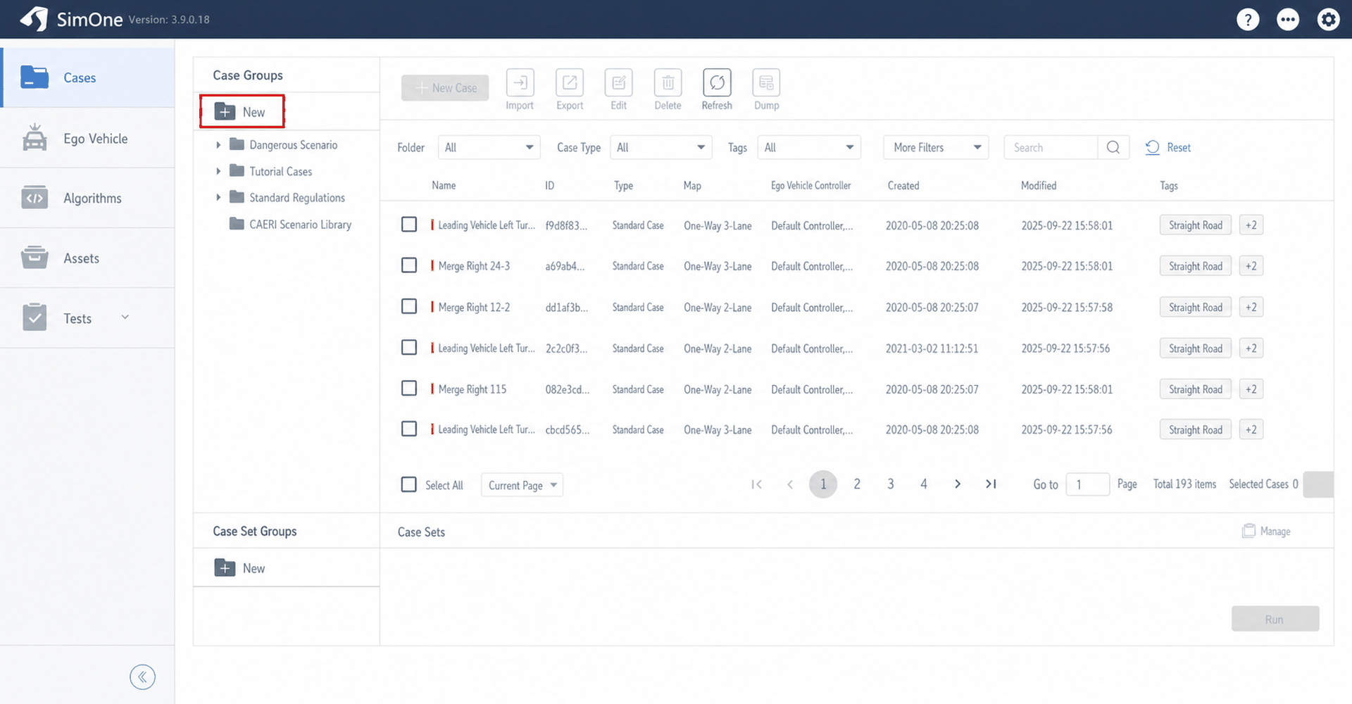
Launch the SimOne simulation software, enter the use case management module, create a new use case group, and set the group name.
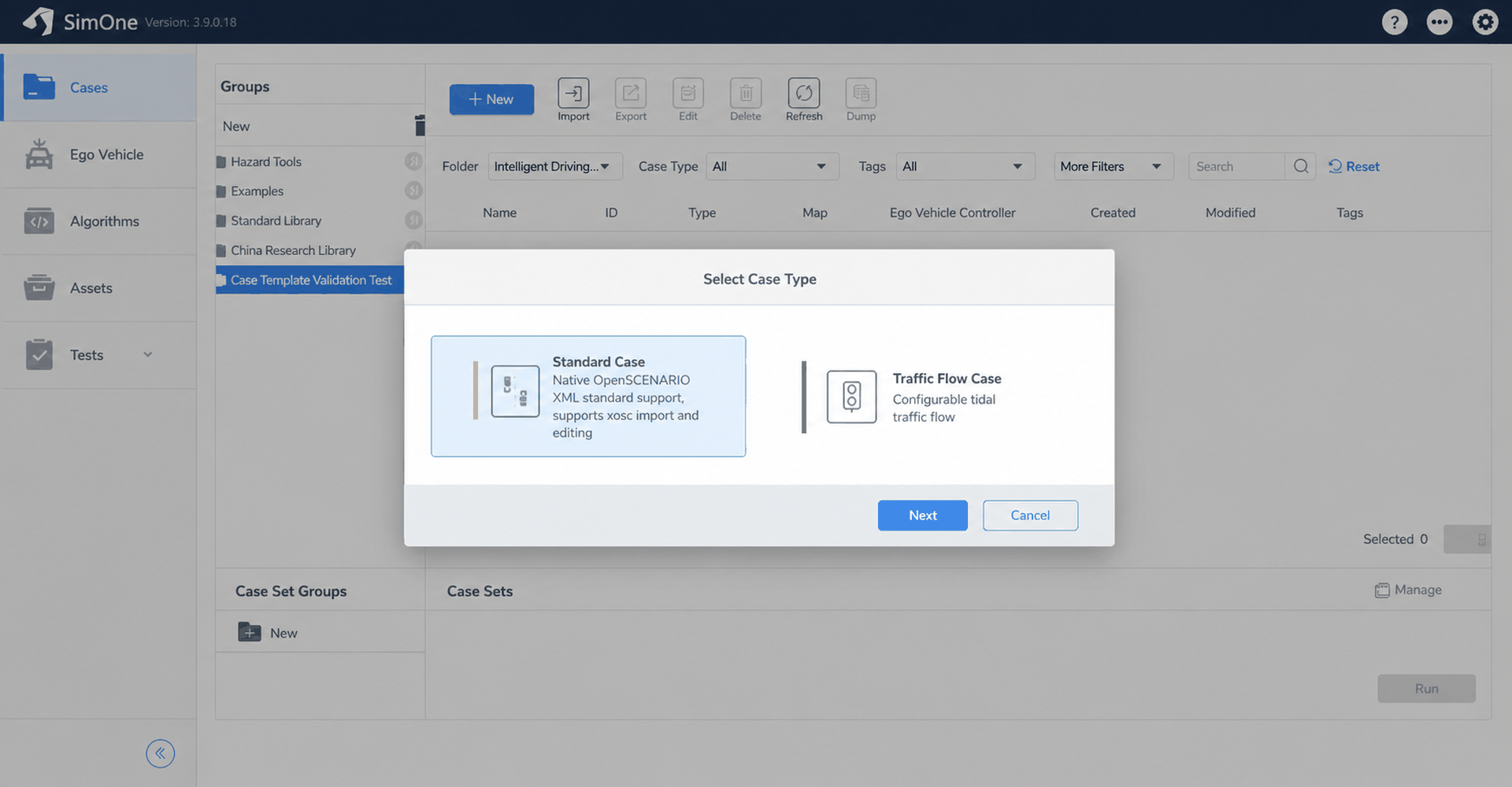
Create a standard use case under this group, select the standard use case type, and define the use case name.
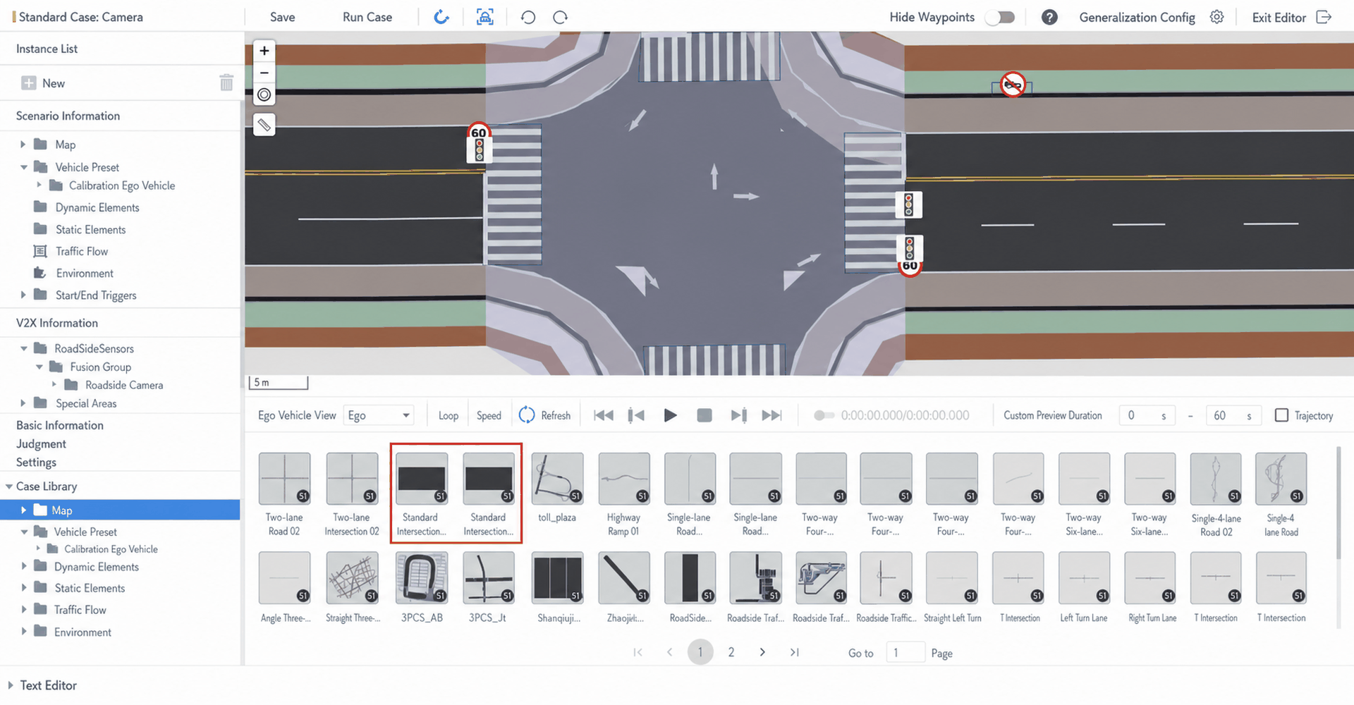
Replace the simulation map with the dedicated checkerboard calibration map. You can select Calibration Room_Reflective 5-Degree Tilted Checkerboard 01 (Calib-Reflect5DegTilt-Checkerboard01, with 5-degree tilt reflective properties) or Calibration Room_Standard BW Checkerboard 01 (Calib-StandardBW-Checkerboard01, standard black-and-white checkerboard).
2.2 Sensor Model and Ego Vehicle Model Setup
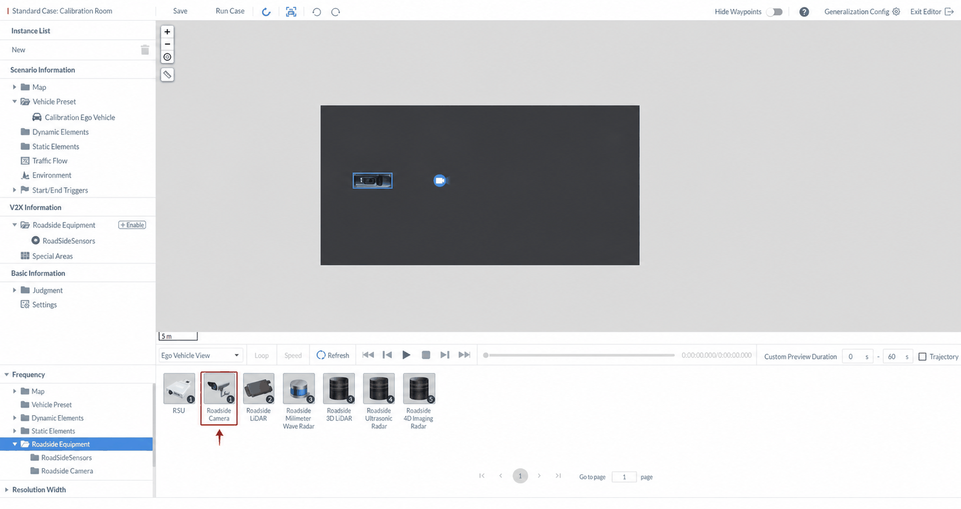
(1) In the Use Case Asset Library panel at the bottom left, click the Roadside Equipment directory, select Roadside Camera, and drag it into the viewport to add it to the current scene.
(2) Set the initial position of the camera sensor to ensure sufficient spatial offset from the checkerboard (world absolute coordinates: (0, 0, 1.5), unit: meters), avoiding model collision or occlusion. Set the sensor orientation to 0° and the checkerboard orientation to 180° (facing the ego vehicle).
(3) Set the initial position of the ego vehicle to ensure it is located behind the camera sensor, avoiding occlusion during simulation.
(4) Set both the absolute target speed and relative target speed of the ego vehicle to 0 to keep the vehicle completely stationary during simulation capture.
2.3 Importing Intrinsic and Extrinsic Parameters
To achieve high-fidelity simulation of the real camera's geometric characteristics, the physical camera's intrinsic and extrinsic parameters must be fully mapped to the virtual camera model.
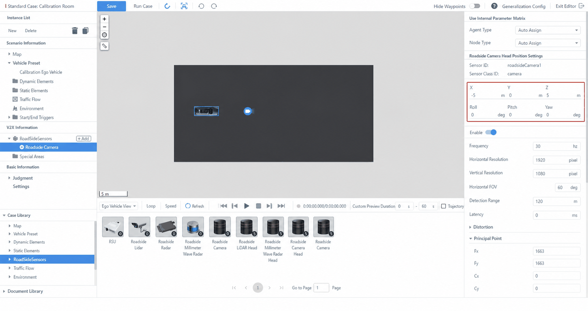
(1) Import extrinsic parameters: In the camera parameter configuration area on the right, set the sensor extrinsic parameters.
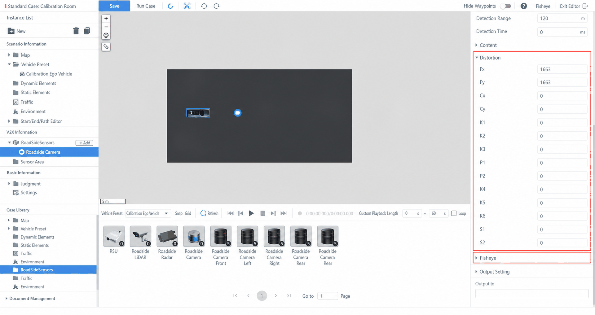
(2) Import intrinsic parameters: In the Distortion Settings area of the camera parameter configuration on the right, enter the intrinsic parameters of the real camera.
(3) Replace the sensor model: Double-click the calibration ego vehicle in the scene, or double-click the calibration ego vehicle icon in the Vehicle Preset directory of the Use Case Asset Library at the bottom left, to enter the ego vehicle editor. Navigate to Sensor → Camera, and delete the initial camera sensor model.
(4) (Optional) Fisheye camera: If the test requires a fisheye camera, clear all parameters under Distortion and switch to the corresponding Fisheye settings.
2.4 Image Rendering and Post-Processing
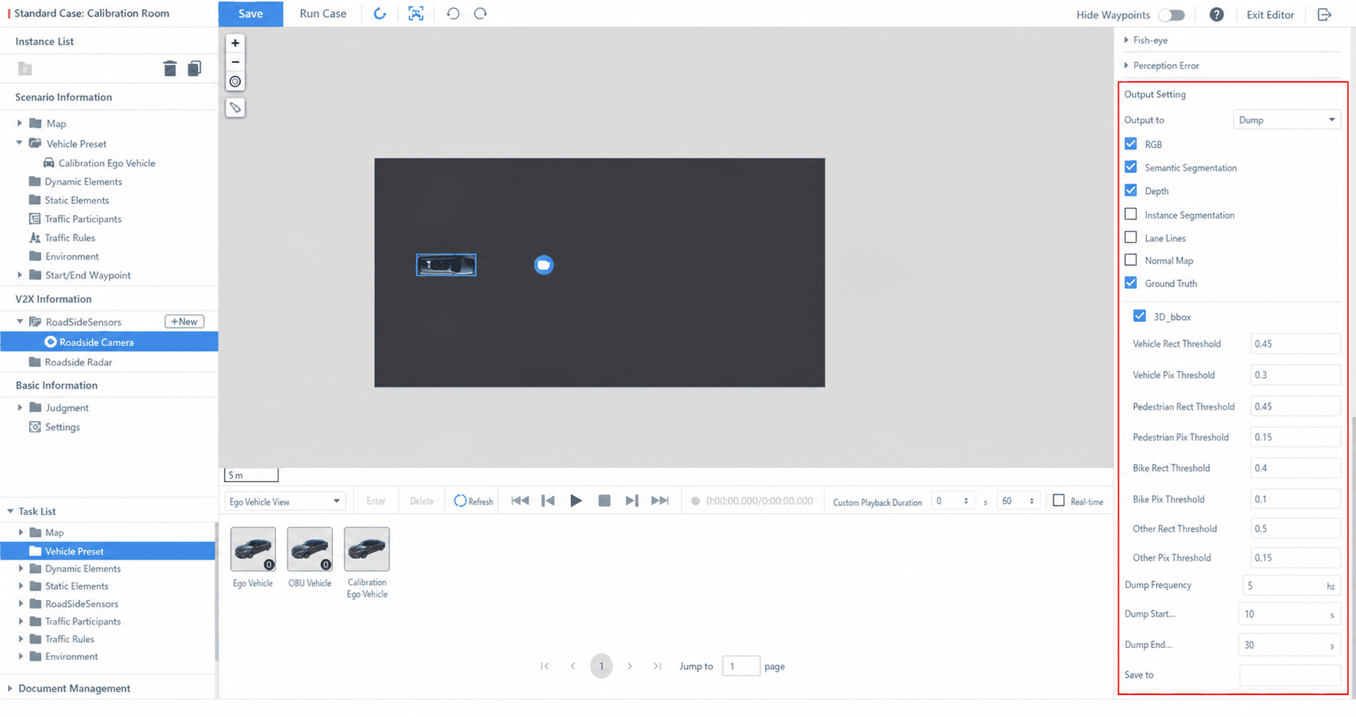
(1) In the scene editor, open the parameter settings page for the roadside camera. In the Output Settings area, set Output To to Dump, and configure the Dump capture frequency (unit: Hz), start and end times, and image file save path.
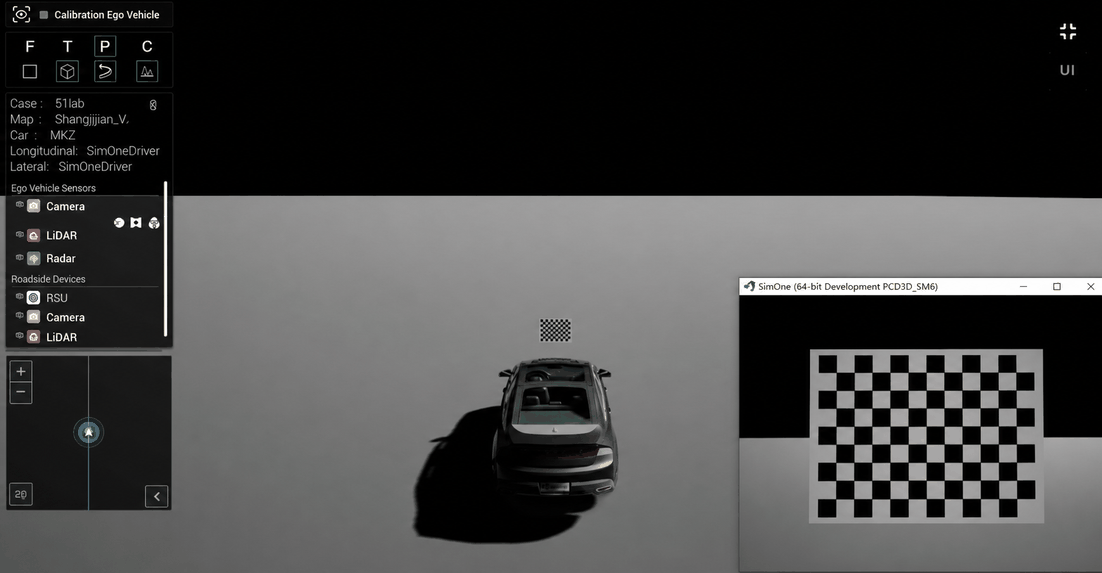
(2) Run the simulation. Raw image data will be written to the specified folder.
(3) Navigate to the Tools folder in the SimOne installation directory and run the RAW2PNG.py script to batch-convert RAW format images to PNG. Configure input and output paths using the following command-line parameters:
--input: Specifies the source folder path containing the RAW image files to be converted. This path should point to the Dump save location set during simulation, and further locate the specific scene and sensor subdirectory. Directory structure:[Dump root directory]/[scene name]/[sensor name].--output: Specifies the target folder path for the converted PNG images. If the specified output directory does not exist, the script will create it automatically. The default is anoutfolder in the directory where the script is executed. To avoid overwriting the raw data, it is recommended to set an independent directory different from the input path.
3. Accuracy Evaluation and Analysis
Compare the simulation images against the real images, calculate the pixel-level error of checkerboard corner points in the image coordinate system, and use corner pixel accuracy and reprojection error as core metrics to quantify the consistency and confidence between simulation and real images.
a) Corner Pixel Accuracy:
Corner pixel accuracy refers to the degree of consistency between the pixel positions of checkerboard corner points in simulation and real images. It is typically expressed as mean error or accuracy rate. For each pair of corresponding real and simulation images, select at least 8 checkerboard corner points (covering various regions of the image) and calculate the pixel accuracy for each corner point using the following formula:

 |
Number of selected corner points |
|---|---|
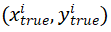 |
Pixel coordinates of the i-th corner point in the real image |
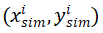 |
Pixel coordinates of the i-th corner point in the simulation image |
 |
Diagonal pixel length of the image |
b) Mean Reprojection Error:
Reprojection error is an important comprehensive metric for evaluating the accuracy of camera parameter calibration. This metric re-projects calibrated 3D spatial points onto the image plane using the calibrated camera parameters, and calculates the Euclidean distance between the resulting projected points and the original image points, thereby quantifying the accuracy of the calibration process. The formula is as follows:

 |
Number of selected corner points |
|---|---|
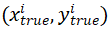 |
Pixel coordinates of the i-th corner point in the real image |
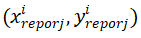 |
Pixel coordinates obtained by re-projecting the 3D coordinates of the i-th corner point in the calibration board coordinate system onto the image plane using the calibrated intrinsic and extrinsic parameters |
4. Full Demo Video
The following video demonstrates the complete operational workflow for the sensor model confidence test: