DIL: Driver-in-the-Loop Testing — Driving Mode Configuration
This tutorial currently applies to SimOne – Enterprise Edition only.
Use this tutorial to learn how to configure driving mode through test case walkthroughs. You can freely configure the driver's perspective, dashboard, center console, rear-view mirrors, and more.
How to Configure Driving Mode
Why Configure Driving Mode?
Driving mode is typically used together with a driving simulator product. Its primary purpose is to adapt the display output to the different monitor arrangements found in driving simulators, which differ from conventional display setups.
1. Configure Nodes
Tip
In a distributed system, after configuring the driving simulator Agent, you must first complete the following steps to configure the driving simulator nodes so that they can support the execution of driving simulator algorithms.
Once the node configuration is complete, you can set up the driving simulator algorithm and start the simulator.
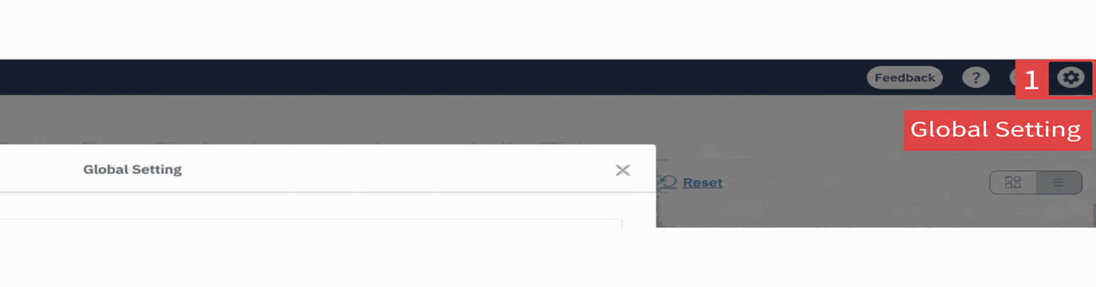
(1)Go to Global Settings → Agent List Management and select an Agent.

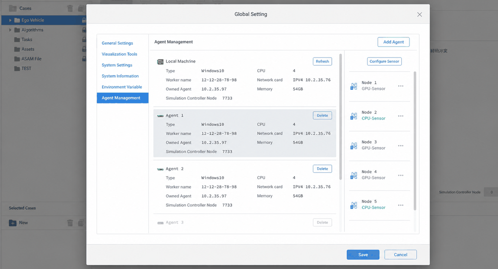
(2)Add a new node.
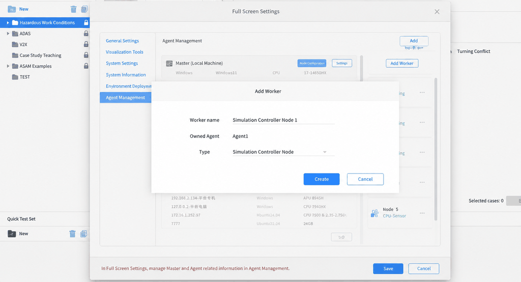
(3)Enter the node name, select the desired Node type, click Create, and then click Save.
2. Configure the Algorithm
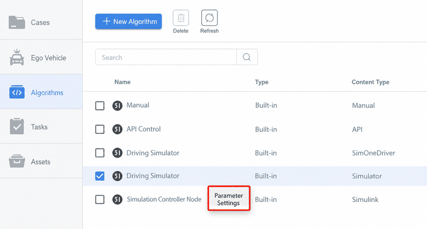
(1)In Algorithm Management, select Driving Simulator (or choose Driving Simulator when creating a new algorithm), right-click and select Parameter Settings, then select the node you just configured.
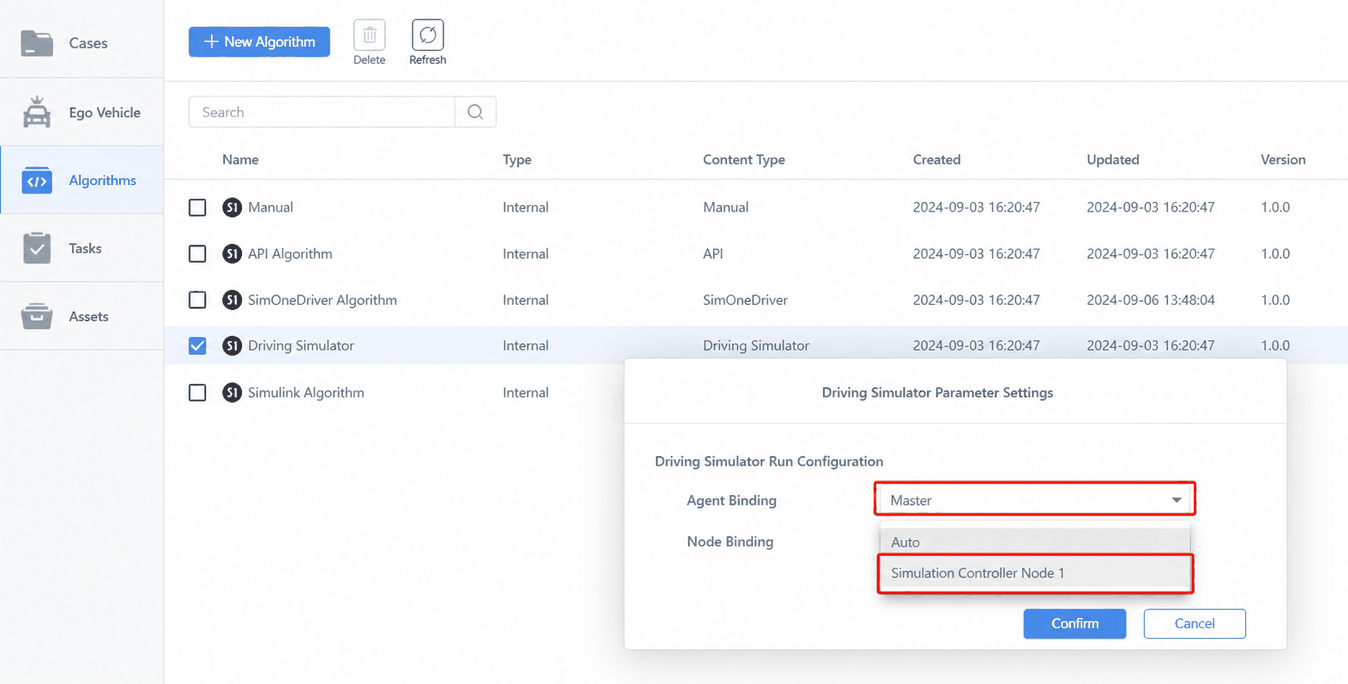
(2)Select the Agent and Node.
3. Configure the Ego Vehicle Model
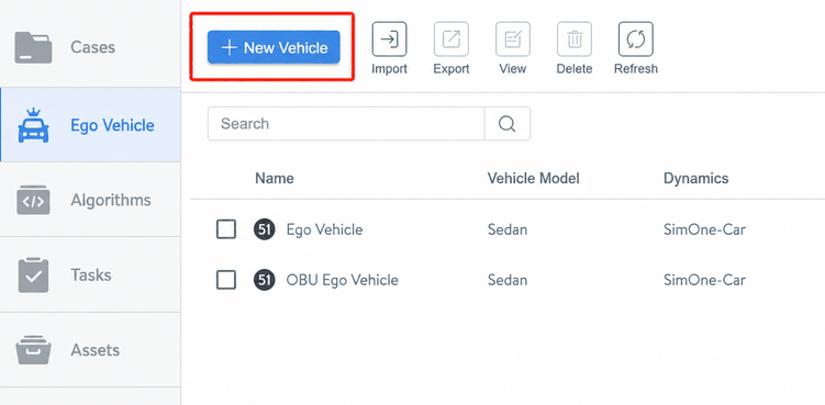
(1)Go to Ego Vehicle Management → Create New Ego Vehicle.
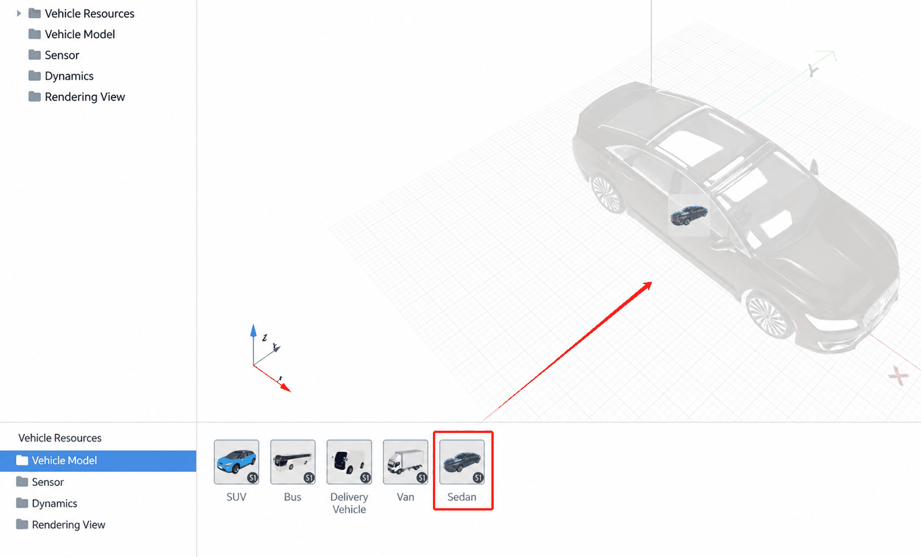
(2)The Ego Vehicle Editor opens automatically. Drag in the Ego Vehicle model you want to configure.
4. Configure Dynamics
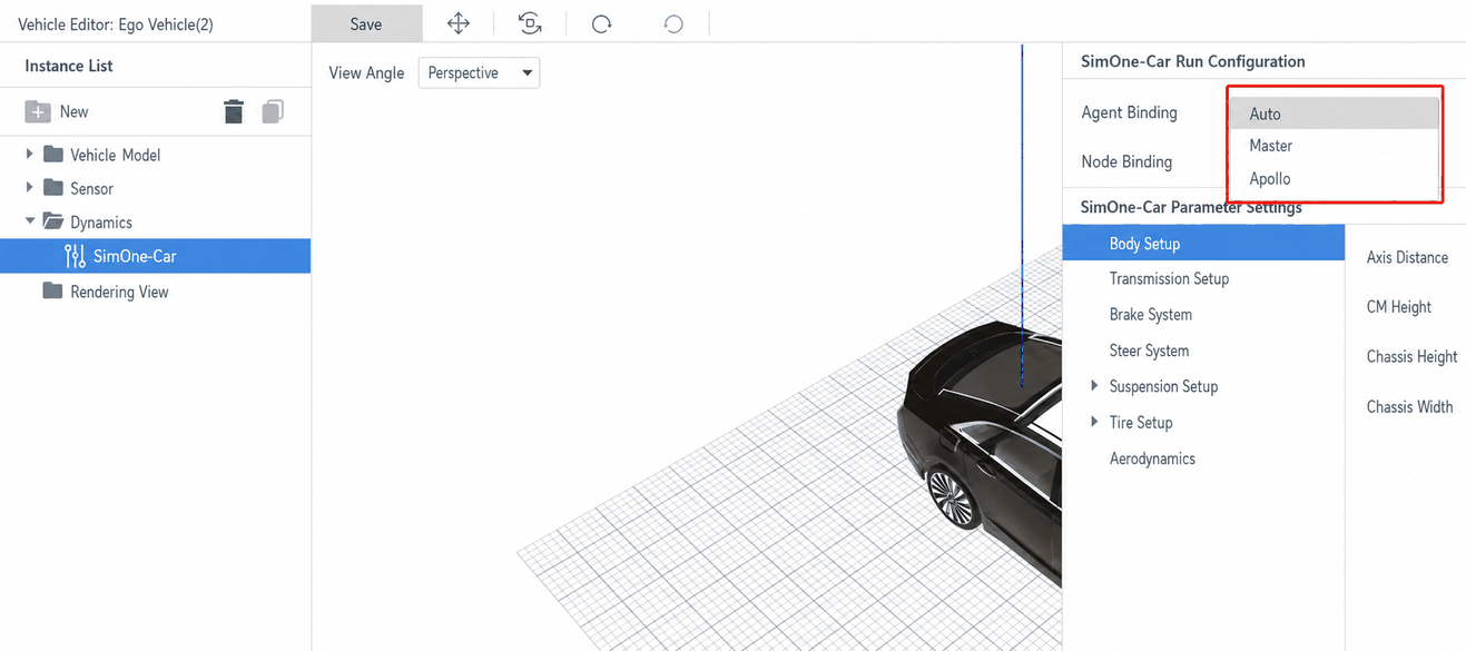
(1)In the Ego Vehicle Editor, click the Dynamics folder SimOne-Car in the left panel, then select an Agent.
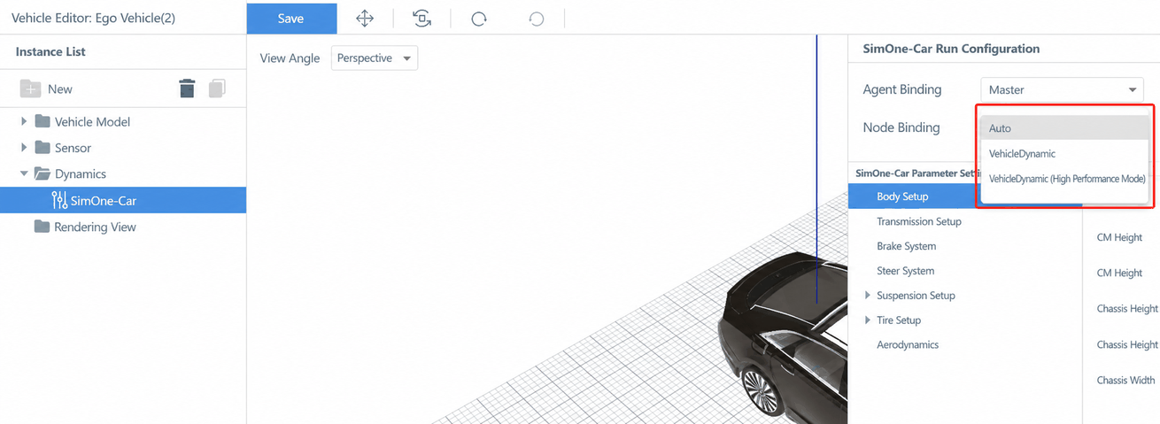
(2)Select a Node.
5. Configure the Render Window
5.1 Preparation
- Purpose: Needed to correctly enter the window origin coordinates and window resolution when configuring render windows.
- Tool required: A screenshot utility (e.g., Snipaste).
5.2 Record the Window Origin Coordinates
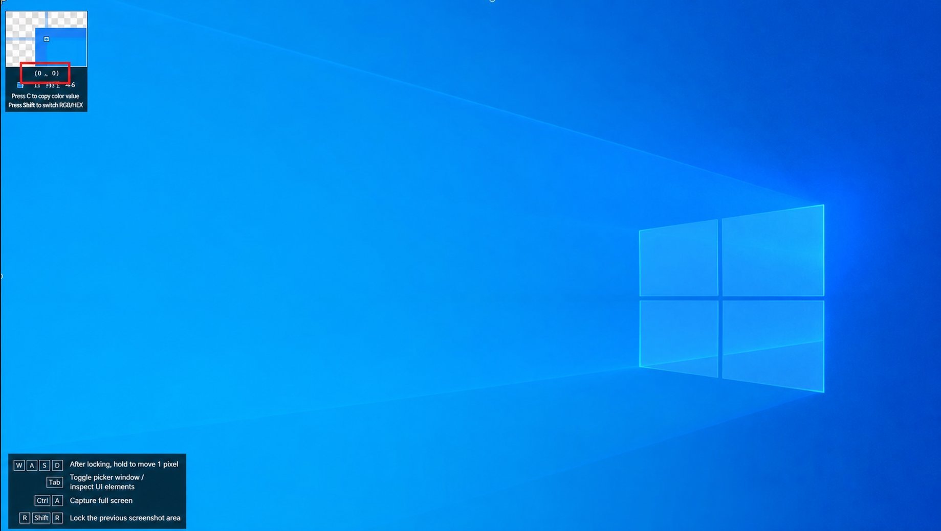
Open the screenshot utility and move the cursor to the upper-left corner of the target display. Record the coordinates (highlighted by the red box) — these coordinates will be used as the window origin.
5.3 Record the Window Resolution
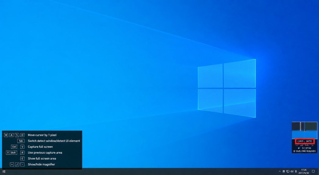
Open the screenshot utility and move the cursor to the lower-right corner of the target display. Record the coordinates (highlighted by the red box). Subtract the window origin coordinates from these values to obtain the window resolution.
5.4 Configure the Driver Seat
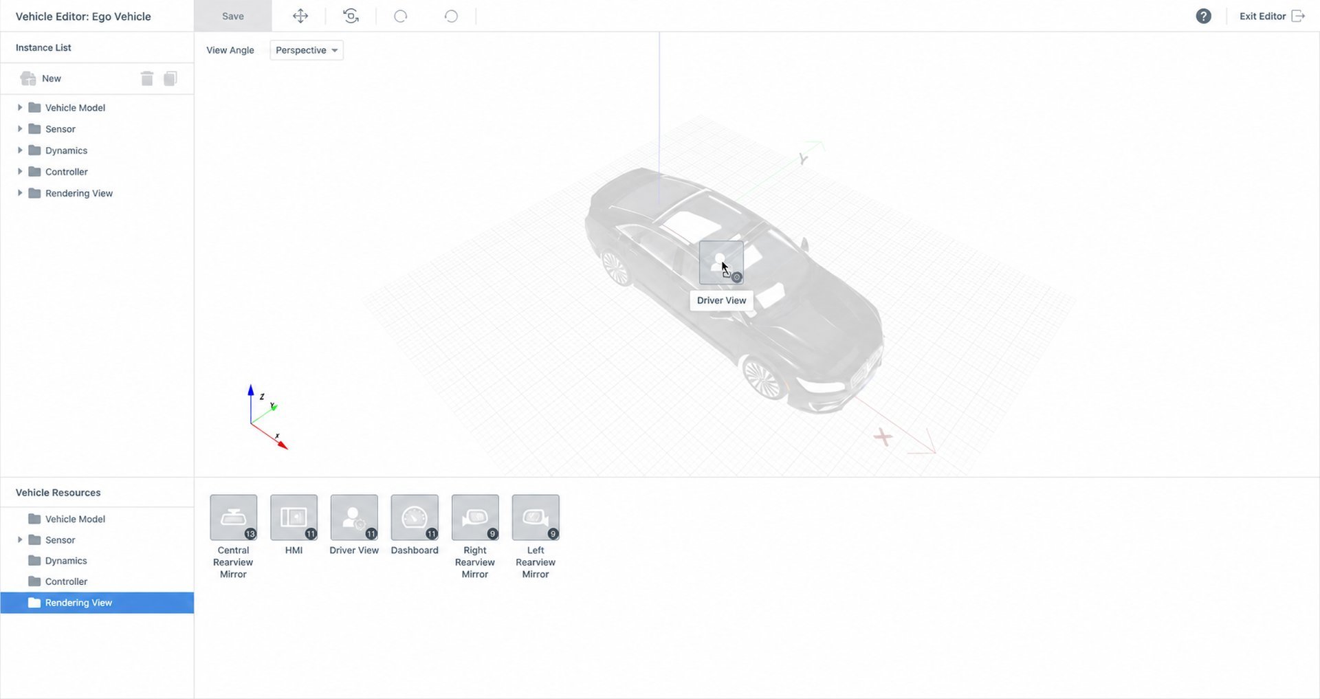
(1)Go to Ego Vehicle Asset Library → Render Window and drag in the Driver Seat.
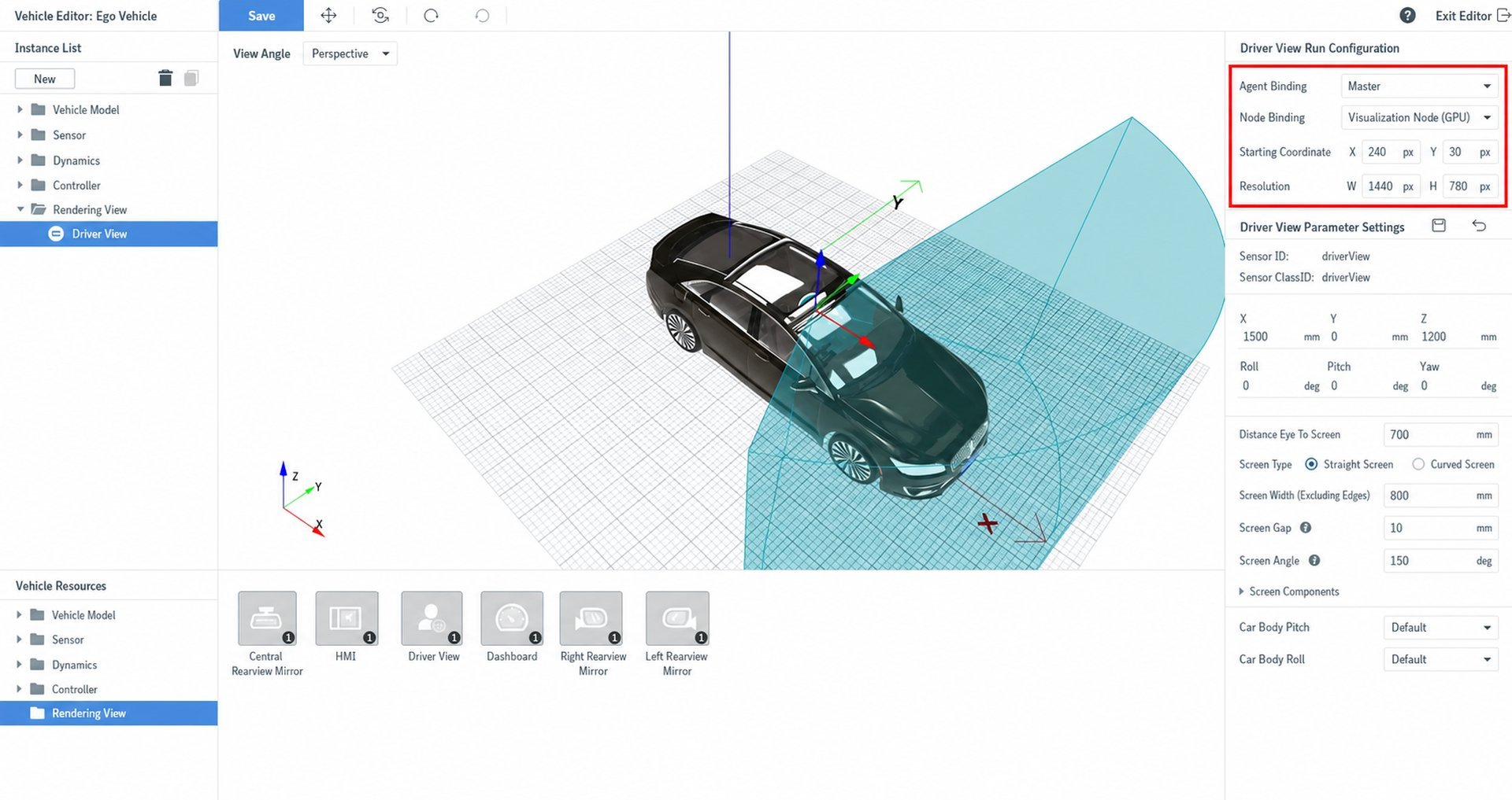
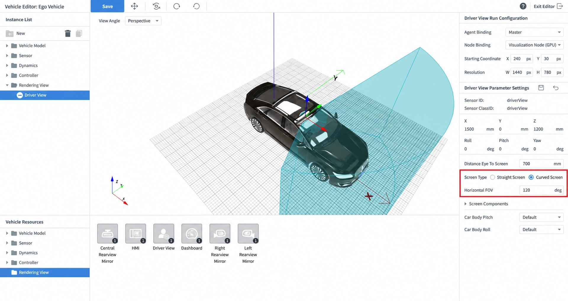
(2)In Ego Vehicle Asset Library → Render Window, edit the run configuration:
- Select Agent
- Select Node as the visualization node (GPU)
- Enter the window origin coordinates (refer to "Preparation – Record Window Origin Coordinates")
- Enter the window resolution (refer to "Preparation – Record Window Resolution")
Tip
The settings here will override the startup parameters of the selected visualization node — that is, the settings here take higher priority.
*The startup parameters referred to here are the startup command-line parameters that can be entered by selecting Edit when adding a physical-level sensor node (GPU) in the agent configuration interface under Settings. For details, see User Reference Manual – Sensor Simulation – Physical-Level Sensor Render Configuration. If a driver seat or rear-view mirror is bound to that node, the node will generate a visualization viewport based on the display range configured here to meet the actual display requirements of the driving simulator.
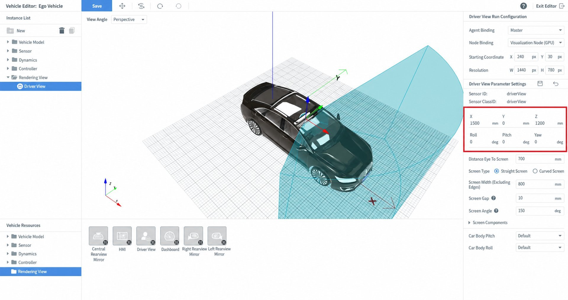
(3)Set the physical coordinates of the render window.
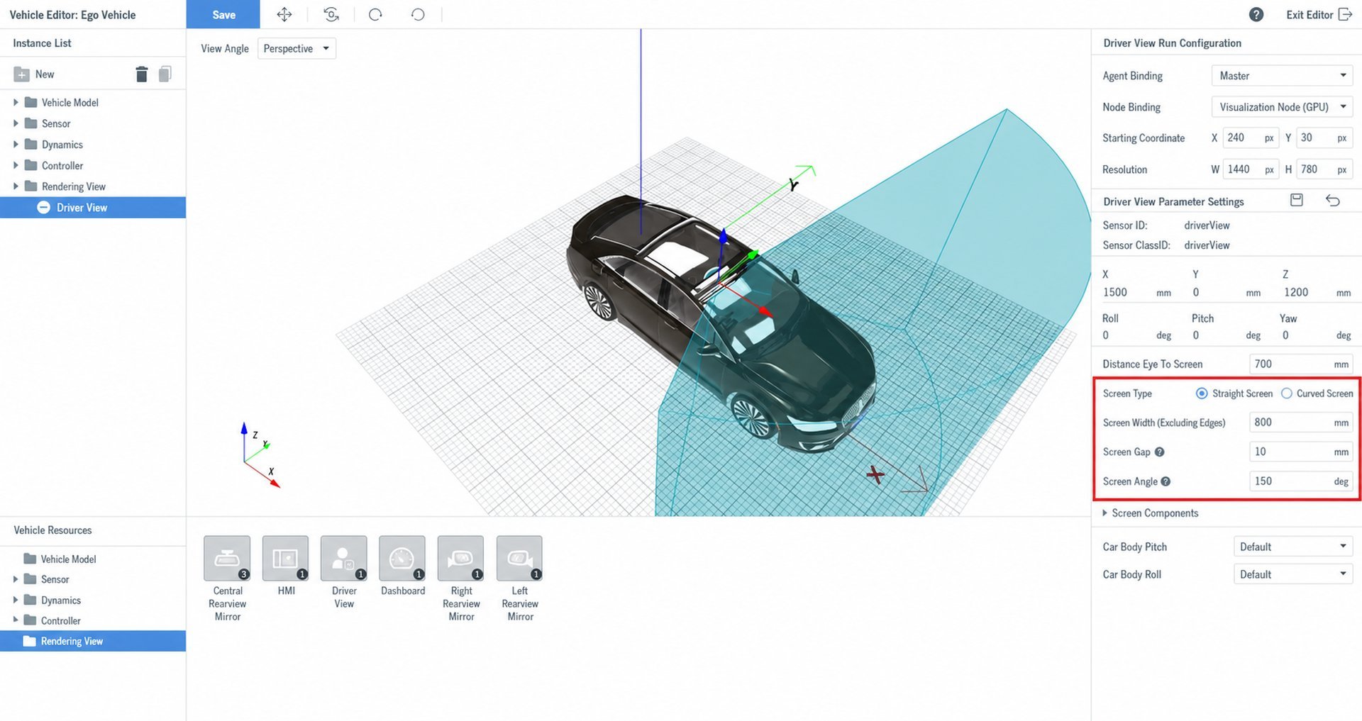
- If the display screen is flat:
(1)Select the screen type as Flat. (2)Enter the screen width (excluding the bezel). (3)Enter the gap between screens. (4)Enter the angle between screens.
- If the display screen is curved:
(1)Select the screen type as Curved. (2)Enter the horizontal FOV.
5.5 Configure Rear-View Mirrors
The configuration steps for the left, center, and right rear-view mirrors are identical. The following example uses the left rear-view mirror.
(1)Go to Ego Vehicle Asset Library → Render Window and drag in the rear-view mirror.
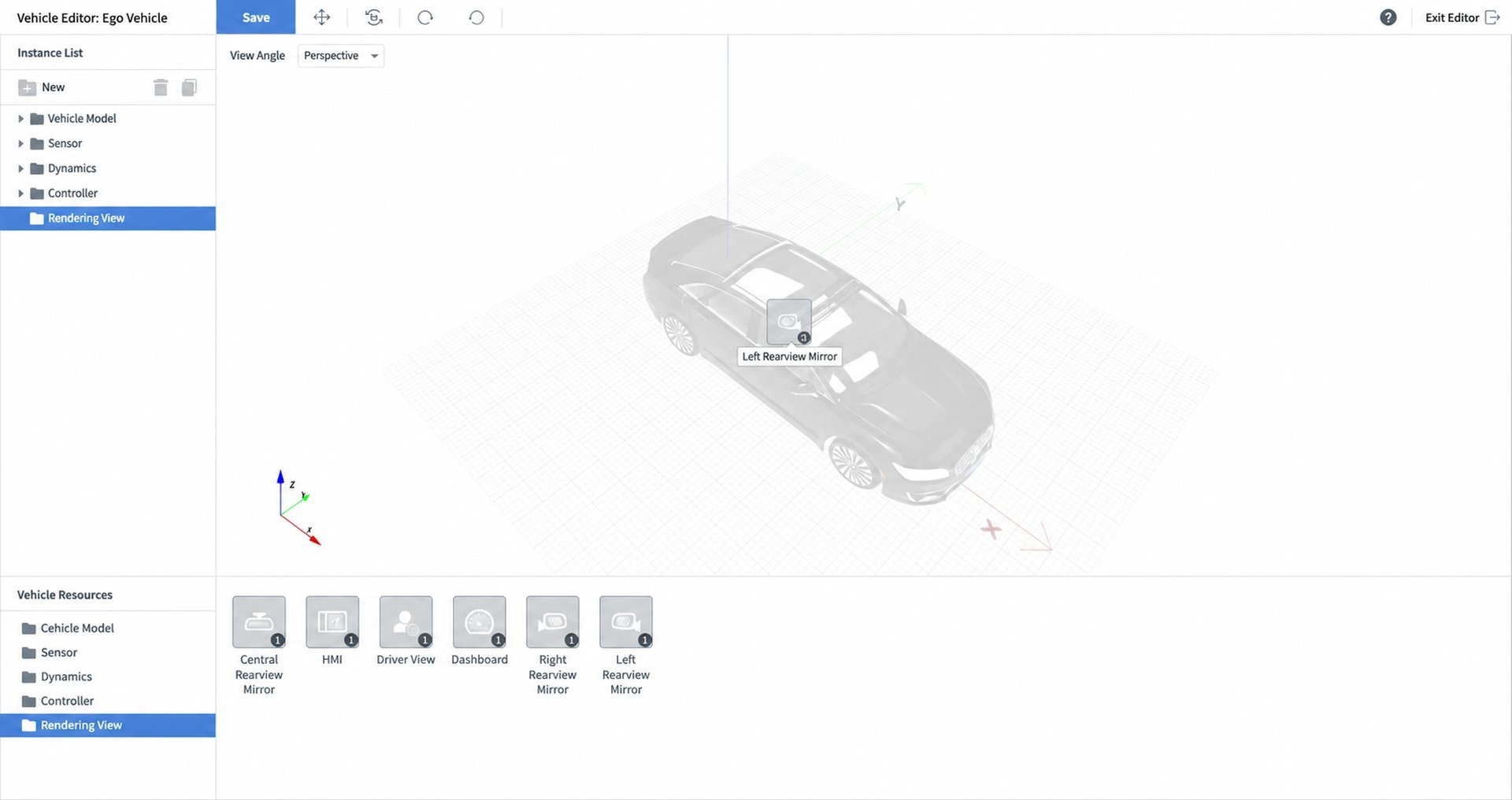
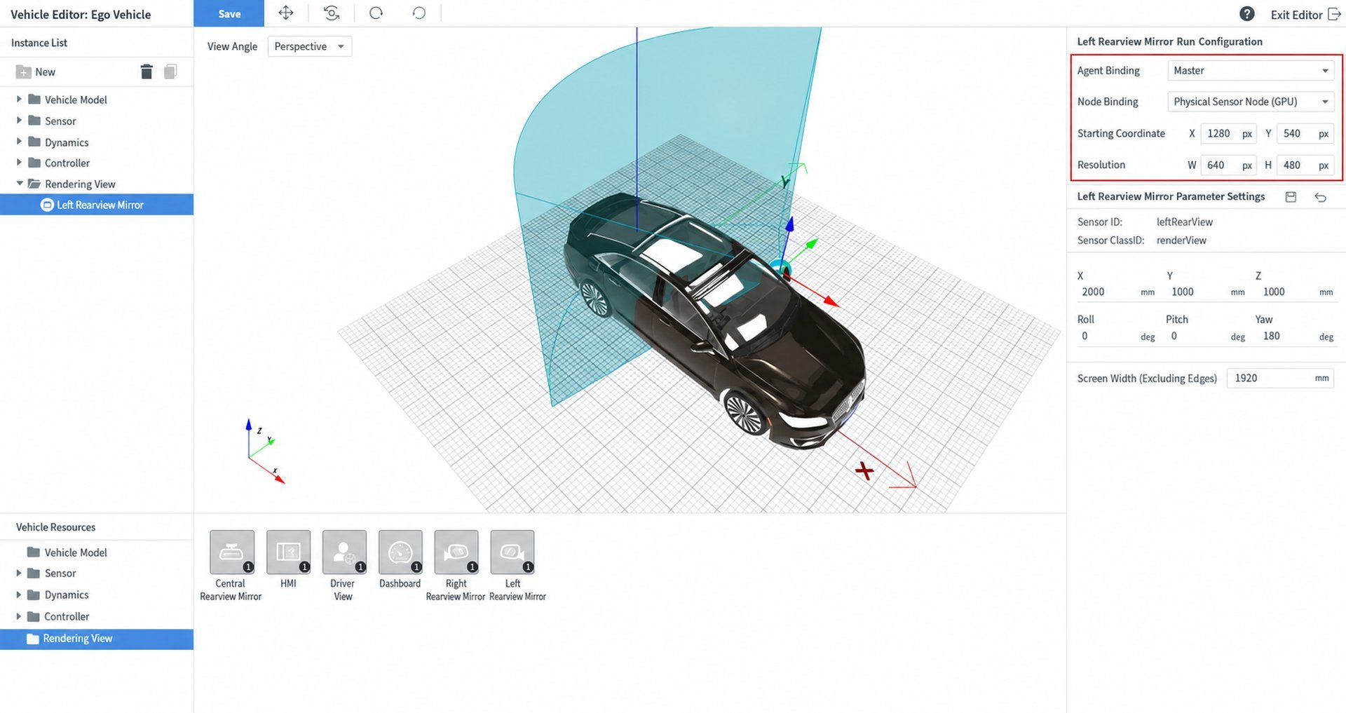
(2)In Ego Vehicle Asset Library → Render Window → Rear-View Mirror, edit the run configuration:
- Select Agent
- Select Node as the visualization node (GPU)
- Enter the window origin coordinates
- Enter the window resolution
Tip
The settings here will override the startup parameters of the selected visualization node (GPU) — that is, the settings here take higher priority.
(3)Set the physical coordinates of the render window.
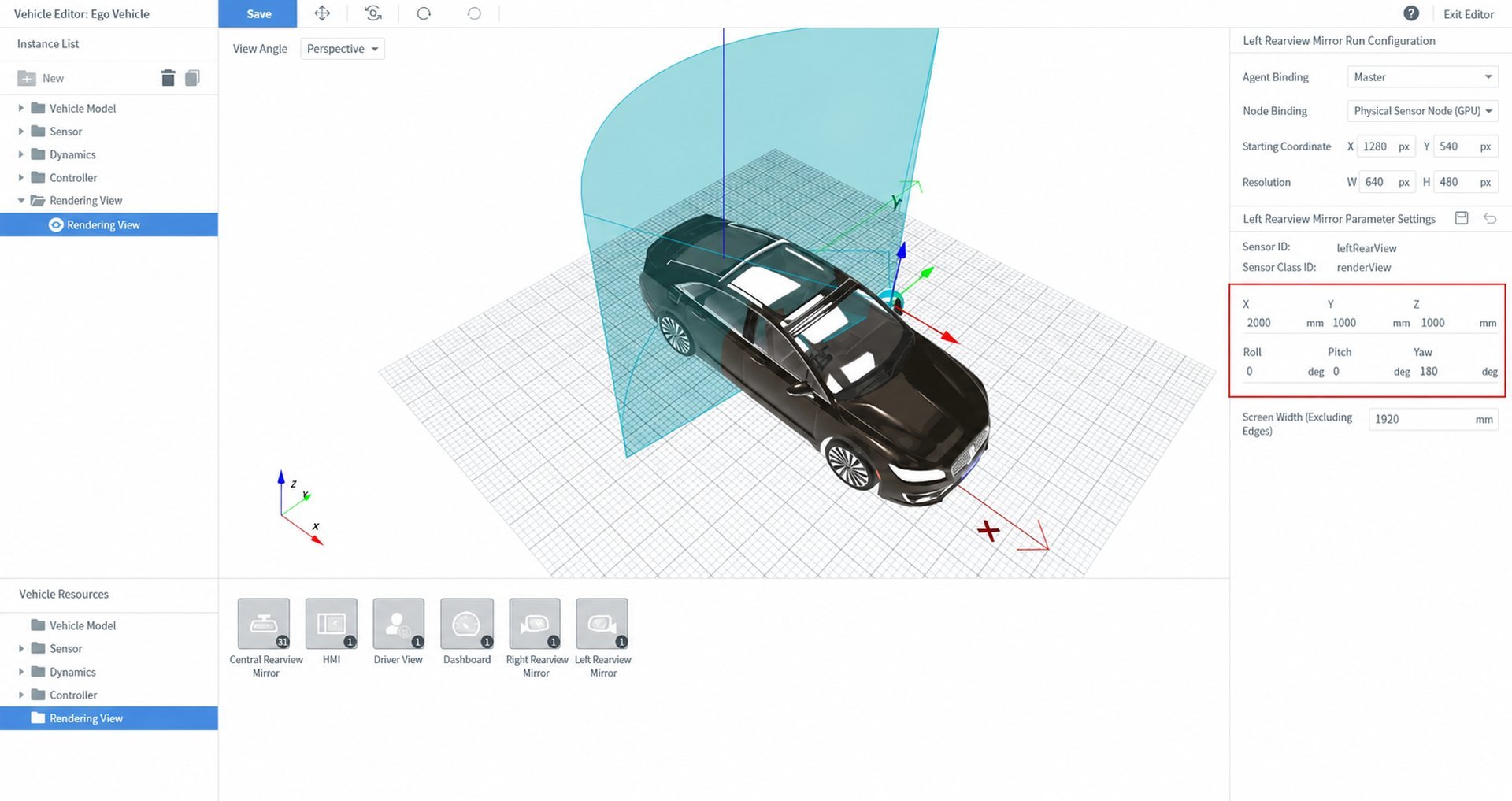
(4)Enter the screen width (excluding the bezel).
5.6 Configure the Dashboard
(1)Go to Ego Vehicle Asset Library → Render Window and drag in the Dashboard.
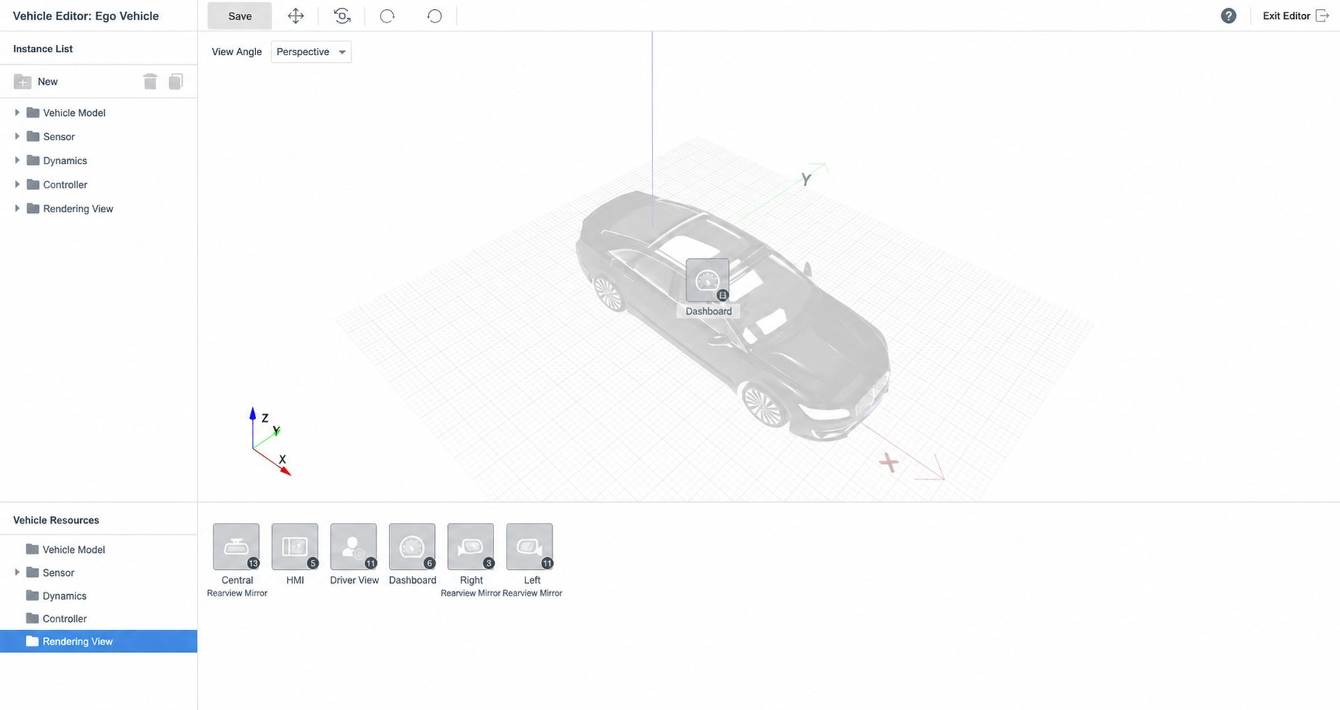
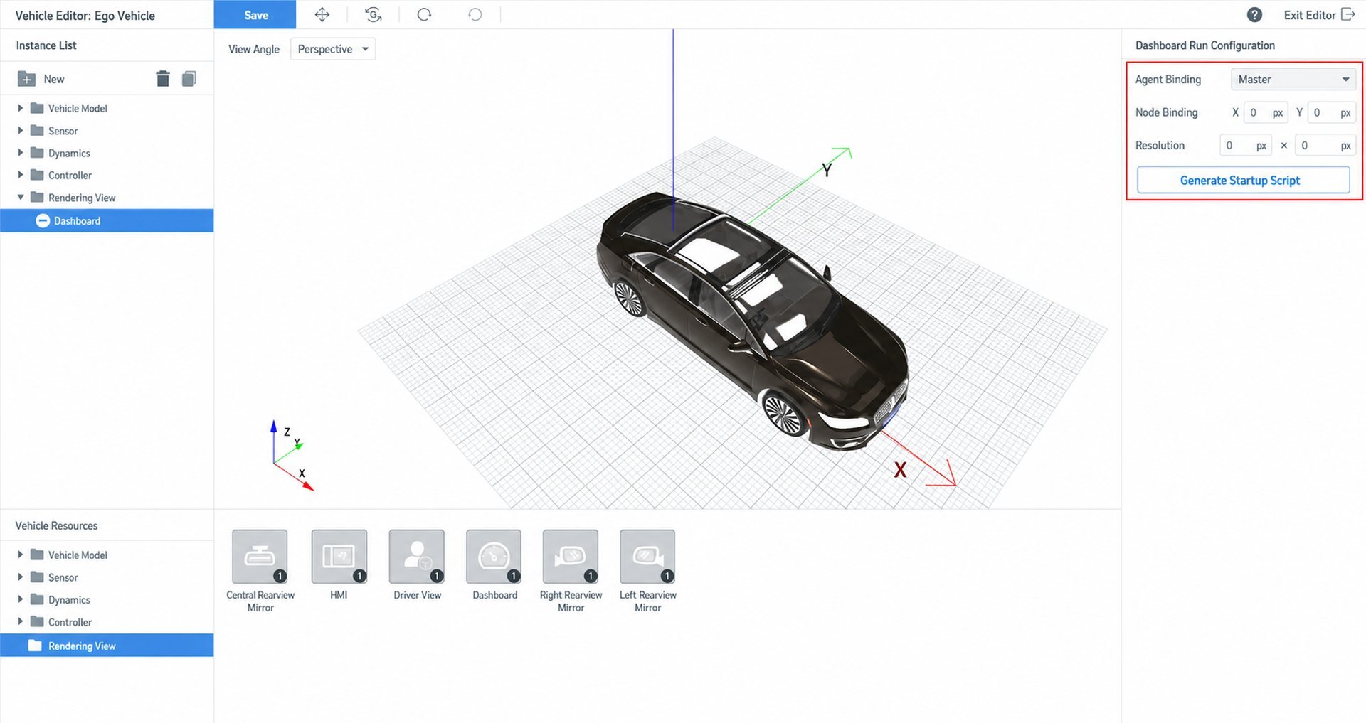
(2)In Ego Vehicle Asset Library → Render Window → Dashboard, edit the run configuration:
- Select Agent
- Enter the window origin coordinates (refer to "Preparation – Record Window Origin Coordinates")
- Click Generate Startup Script
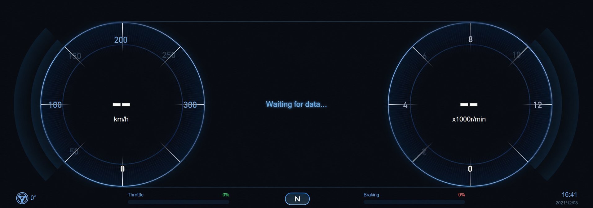
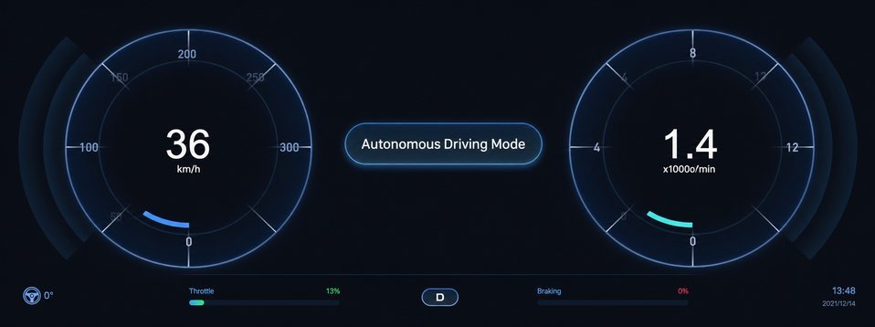
(3)The target window opens the dashboard interface automatically.
- When idle, it shows a waiting-for-data state:
- During test case execution, it displays real-time data:
5.7 Configure the Center Console
(1)Go to Ego Vehicle Asset Library → Render Window and drag in the Center Console.
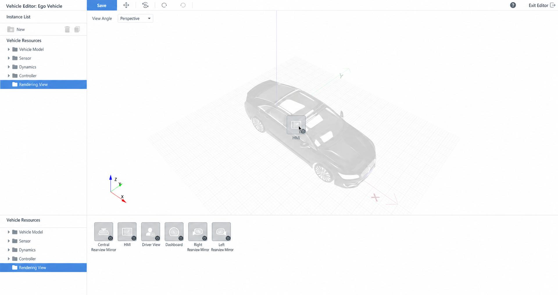
(2)In Ego Vehicle Asset Library → Render Window → Center Console, edit the run configuration:
- Select Agent
- Enter the window origin coordinates (refer to "Preparation – Record Window Origin Coordinates")
- Click Generate Startup Script
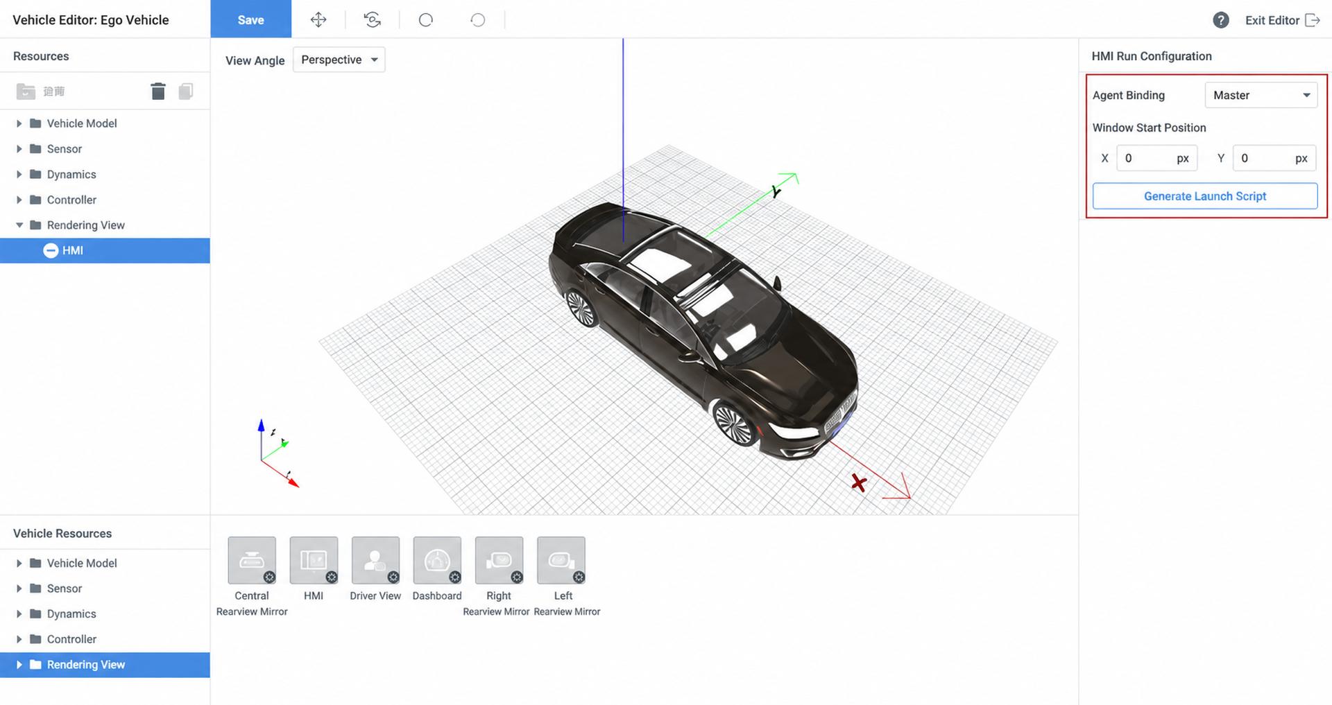
(3)The target window opens the center console interface automatically.
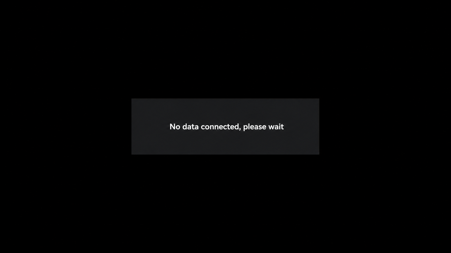
-
When idle, it shows a waiting-for-data state:
-
During test case execution, it displays real-time data: