Editing Scene Elements (OpenScenario)
This tutorial walks through the complete workflow for creating a test scenario that conforms to the OpenSCENARIO standard, covering: ① Introduction to the Standard Case Editor interface, ② Editing the initial state and behavior planning of test objects, ③ Using triggers, ④ Setting up actions, ⑤ Defining end conditions, and ⑥ Previewing the scenario.
1. Adding Test Objects and Setting Their Initial State
1.1 Case Editor Interface Overview
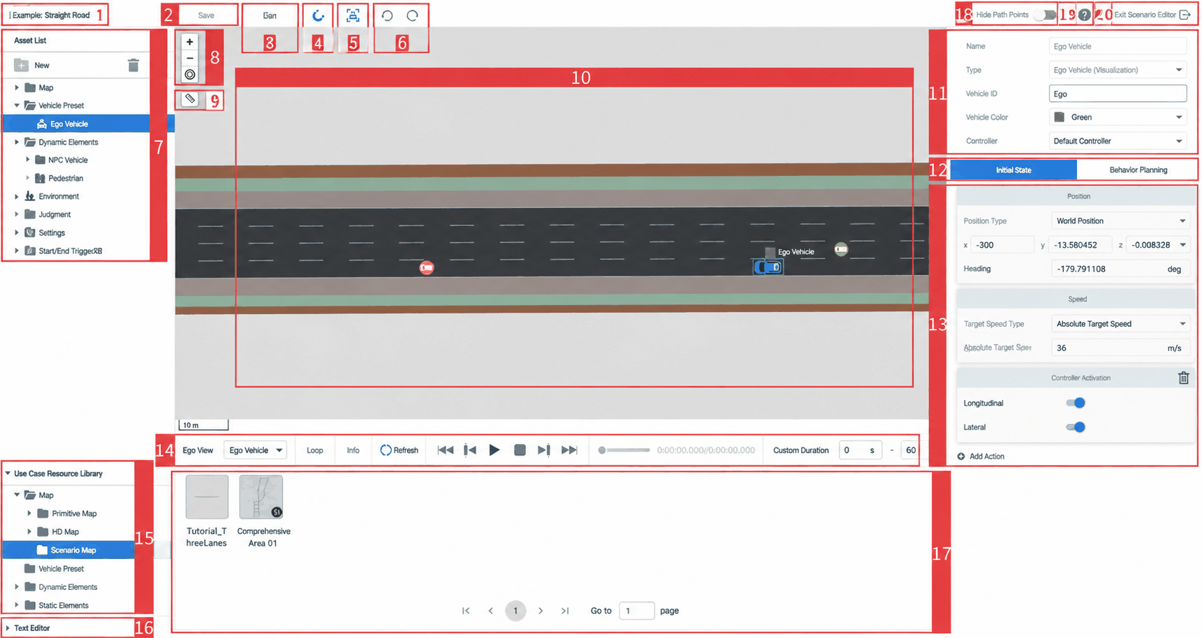
| ID | Item | Description |
|---|---|---|
| 1 | Case Name | Displays the name of the current case |
| 2 | Save Button | Click to save the case after making edits |
| 3 | Run Case Button | When edits have been made in the Case Editor, click to open the New Task dialog. Select the Ego Vehicle type to run the case directly. |
| 4 | Snap to Lane Center | When active, waypoints added for the ego vehicle or dynamic elements will snap to the center of the lane the cursor is over |
| 5 | Follow Ego Vehicle | During trajectory preview, the viewport follows the ego vehicle |
| 6 | Undo / Redo | Revert to the previous / next operation |
| 7 | Resource List | Lists the assets displayed in the right-side Case Editor |
| 8 | Viewport Controls | Includes zoom in, zoom out, and center on ego vehicle |
| 9 | Distance Tool | Click the ruler button — the cursor changes to a crosshair. Click and drag in the map area to measure distance. Supports multi-segment measurement: click again to record the distance from the previous point. Right-click or press ESC to exit. |
| 10 | Case Edit Viewport | Edit the case in this viewport: drag in the ego vehicle, dynamic elements, and static elements, then set their trajectories and parameters |
| 11 | Ego Vehicle Properties Panel | Adjust ego vehicle parameters, including vehicle type and controller selection |
| 12 | Tab Toggle | Switches between Initial State and Behavior Planning tabs |
| 13 | Ego Vehicle / NPC Properties | Add actions and set initial states for the ego vehicle or NPC vehicles |
| 14 | Playback Control Bar | Left to right: Loop Playback, Playback Speed, Refresh, Jump to Start, Previous Frame, Play/Pause, Jump to End, Progress Bar, Elapsed/Total Time, Custom Preview Duration |
| 15 | Case Resource Library | Assets available for data-driven case editing |
| 16 | Text Editor | Opens a text editing mode for convenient manual editing |
| 17 | Case Resource Preview | Click a resource in the Case Resource Library on the left to display it on the right |
| 18 | Hide Waypoints | Toggle to hide all waypoints of the ego vehicle and dynamic elements — only trajectories are shown |
| 19 | Help Center | Click to open Help Center documentation |
| 20 | Exit Editor | Click to exit the Case Editor dialog |
1.2 Adding Test Objects
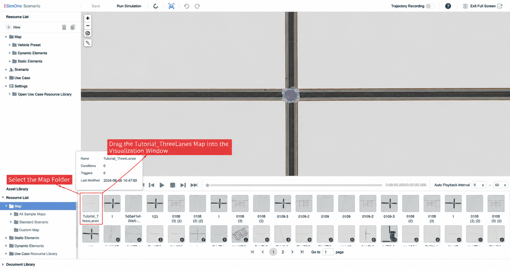
- Since the default map is not suitable for this tutorial, go to Case Resource Library → Maps and select the previously imported
Tutorial_ThreeLanesmap. Drag it into the viewport to replace the current map.
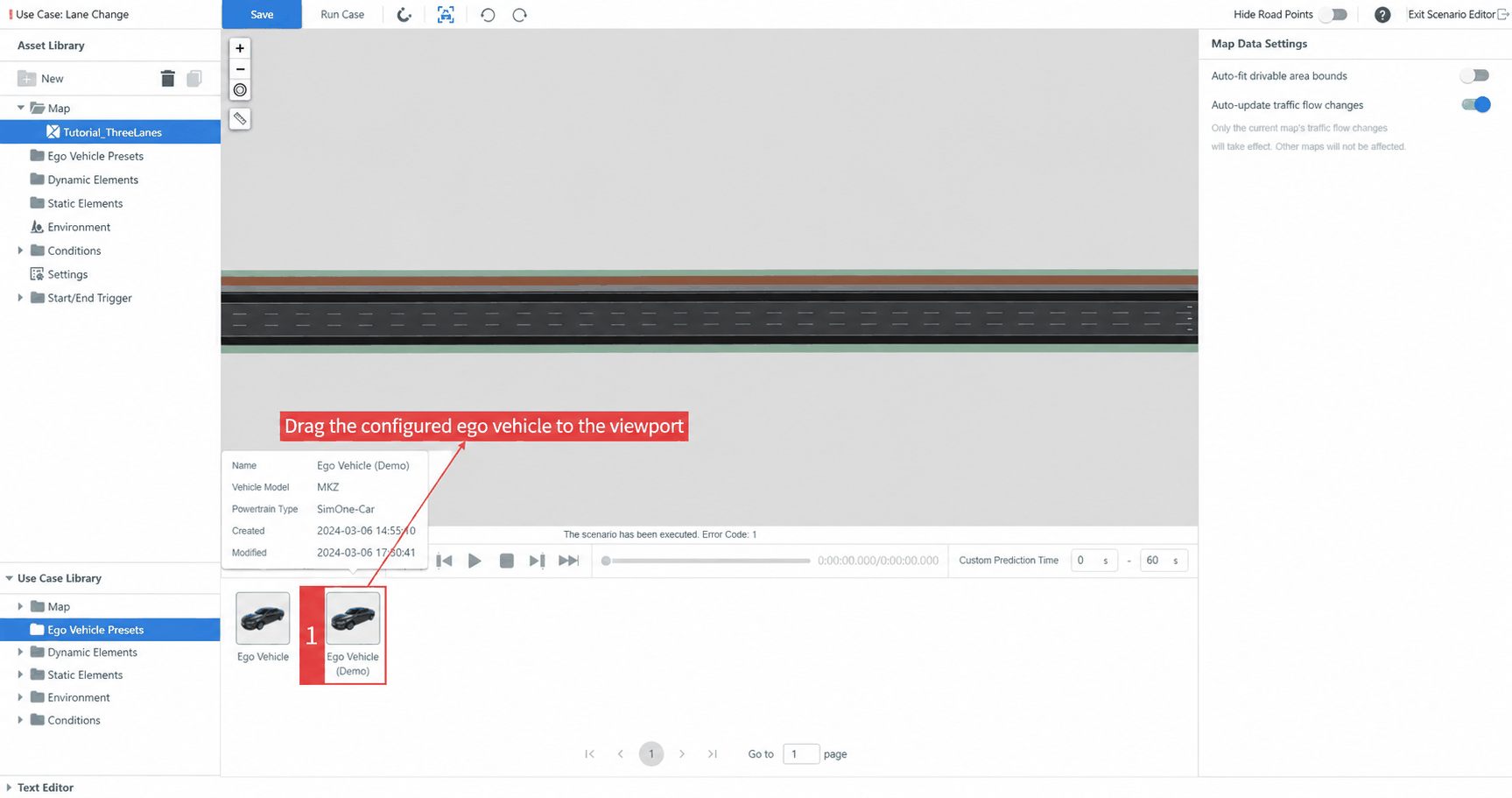
- Go to Case Resource Library → Ego Vehicle Presets and drag the Ego Vehicle (Demo) onto the map.
Left-click the blue vehicle icon to reposition the ego vehicle. The coordinates in the Initial State → Position panel on the right will update accordingly. You can also enter coordinates directly to set the starting position.
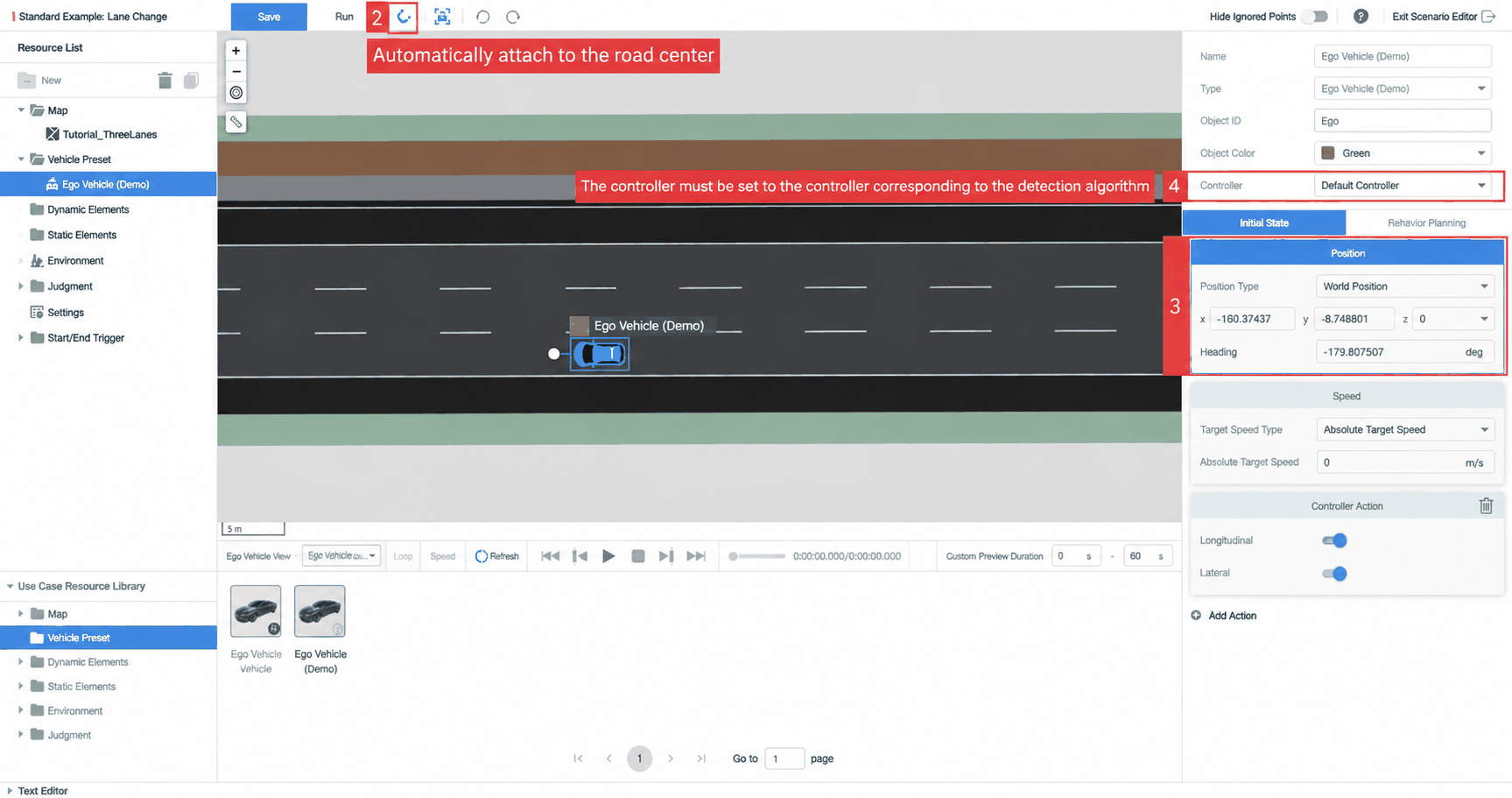
- Set the X coordinate to -300. After releasing the mouse, the ego vehicle will automatically snap to the lane center (because Snap to Lane Center is enabled), and the vehicle heading aligns with the lane direction. Hover over Resource List → Ego Vehicle Presets, then double-click the vehicle name and press Enter to rename the object. Set the ego vehicle's Controller — if no algorithm is connected yet, the default controller is fine.
During testing, you can switch to an ego vehicle with a connected algorithm.
The Controller is the carrier for the algorithm. Assigning different controllers allows the same ego vehicle to be used for different algorithms across different cases — for example, an autonomous driving controller or an AEB algorithm controller.
- Collaborative Edition: Administrators manage the number and names of controllers in the SimOne System Admin page.
- Enterprise Edition: Manage controller names and count in Settings (top-right corner of the main interface).
- Click Case Resource Library → Dynamic Elements, select any standard NPC vehicle (this tutorial uses an AudiA2), and drag it onto the map. Set the AudiA2's X coordinate to -270, placed in the lane adjacent to the ego vehicle. Hover over Resource List → Dynamic Elements, double-click the NPC name and press Enter to rename it.
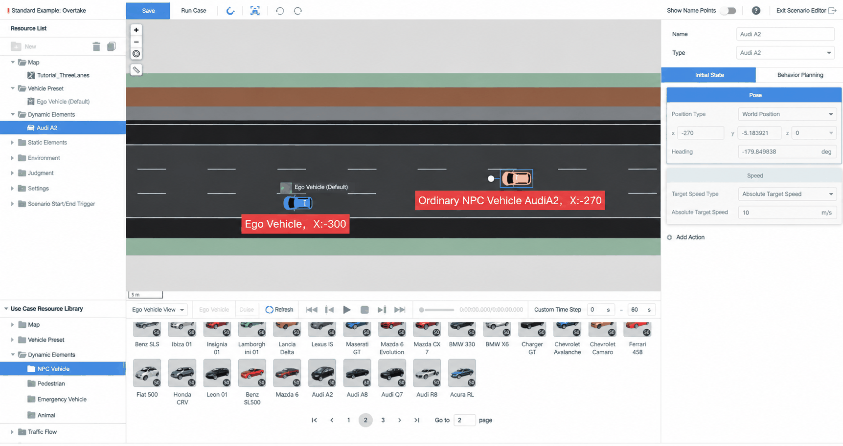
Hold the left mouse button to pan the view; scroll the middle mouse button to zoom.
The buttons in the top-left of the viewport (top to bottom): Zoom In, Zoom Out, Center on Ego Vehicle, Distance Tool.
1.3 Setting the Initial State of Objects
The initial state corresponds to the beginning of the story — the vehicle's state at the very first instant.
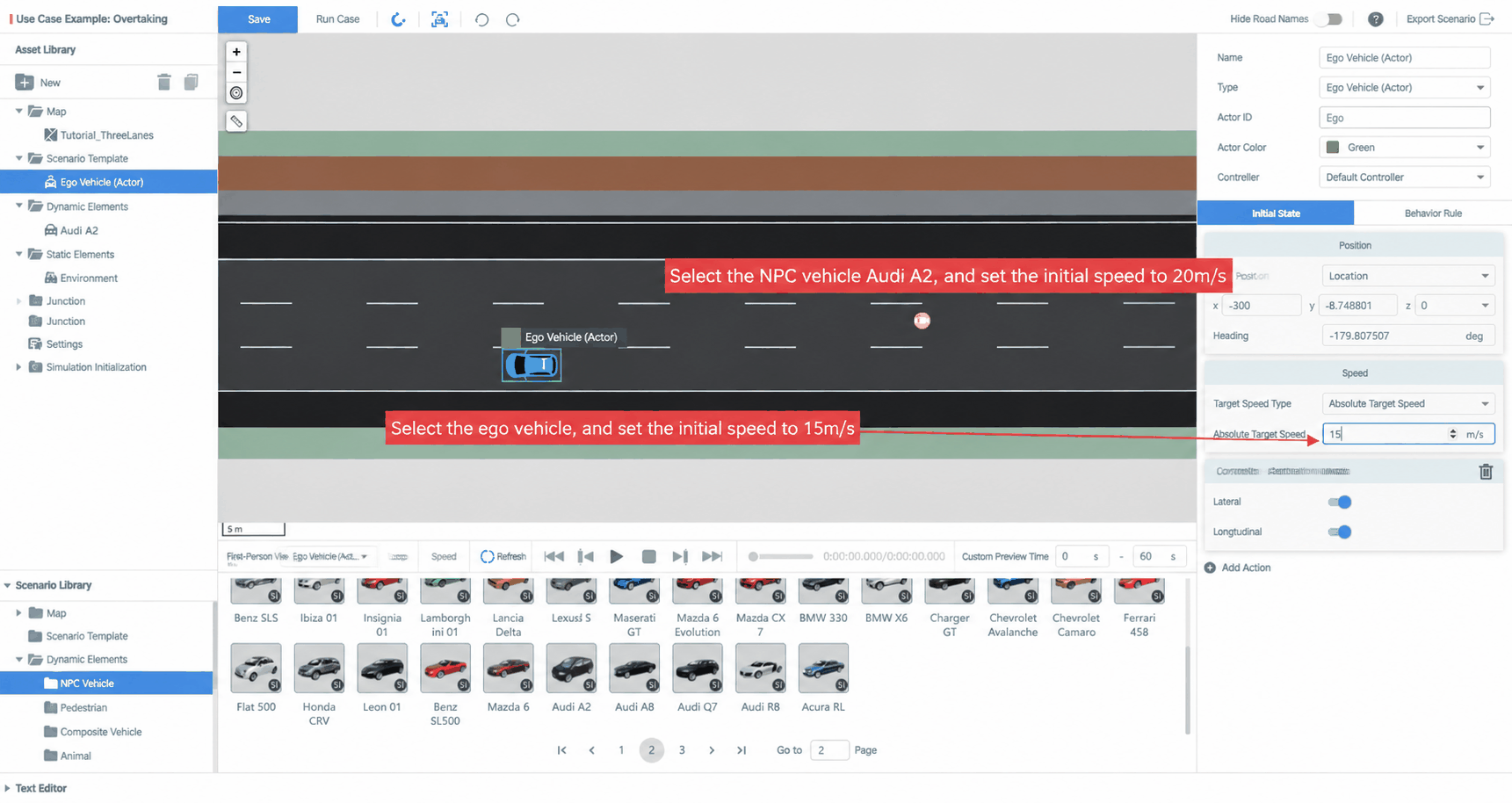
Set the ego vehicle speed to 15 m/s and the NPC AudiA2 speed to 20 m/s.
If a dynamic object only has an initial state configured (no behavior planning), it will travel along a randomly generated route through the road network at its initial speed.
2. Adding Behavior Planning to Test Objects
Behavior planning defines what a dynamic object does and when during the scenario.
Next, we will add a lane-change event to the NPC AudiA2 in the Behavior Planning panel.
2.1 Behavior Planning Structure
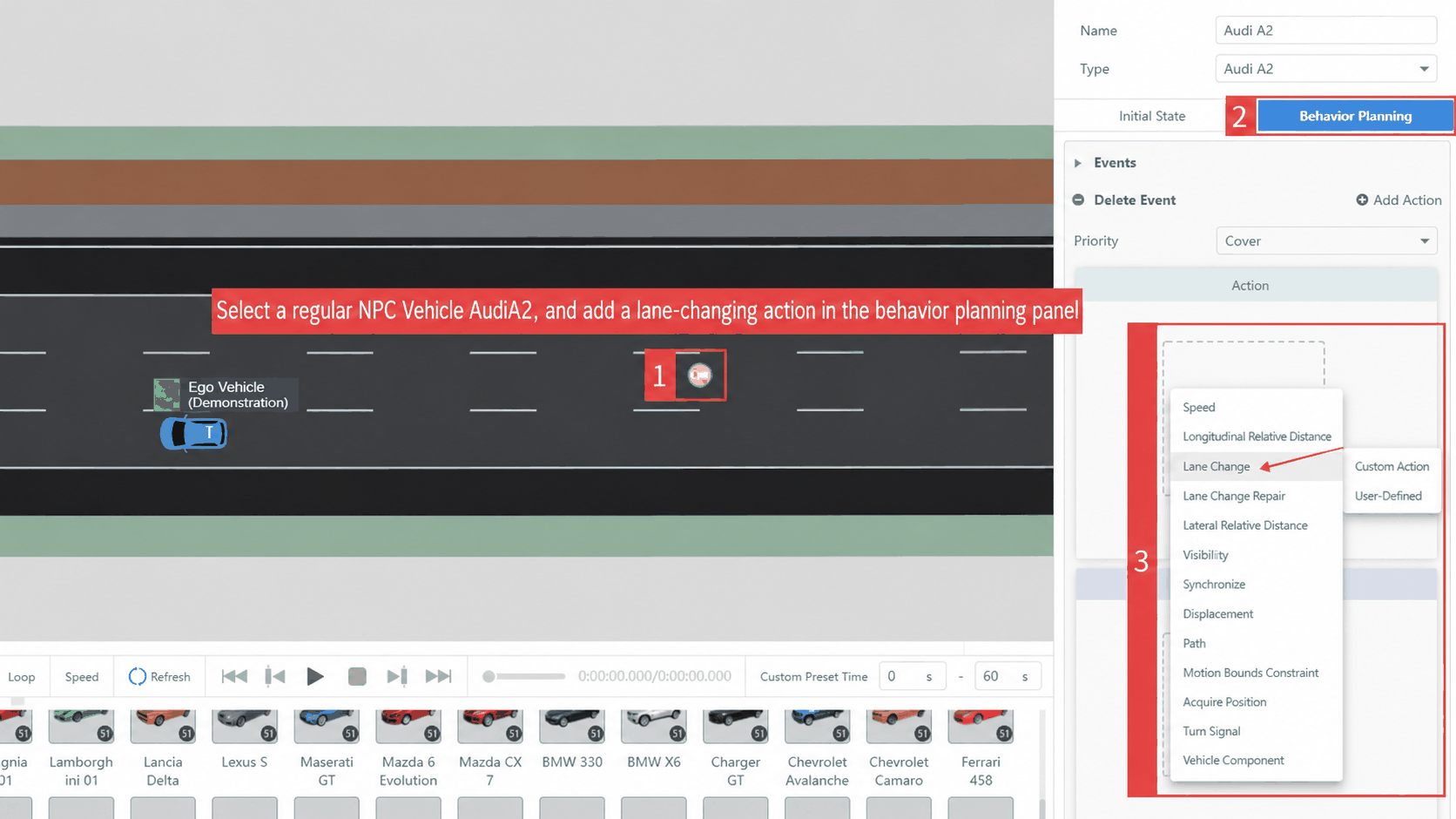
Click the NPC AudiA2, select the Behavior Planning tab in the right-side properties panel, then click Add Event. Behavior planning is organized by Events, and each event can contain multiple actions.
2.2 Adding an Action
To add a lane-change action to the AudiA2, go to Event → Action → Add Action and select Private Action → Lane Change from the dropdown.
2.3 Parameter Configuration
- Change Dimension: Time
- Change Shape: Sinusoidal
- Change Time: 2 s
- Target Lane Mode: Relative target lane (requires specifying a reference object)
- Reference Object: Ego Vehicle (Demo)
- Relative Target Lane: 0 (change to the lane of the reference object)
- Lane Offset: 0 m
These parameters cause the AudiA2 to change from the center lane to the ego vehicle's lane over 2 seconds.
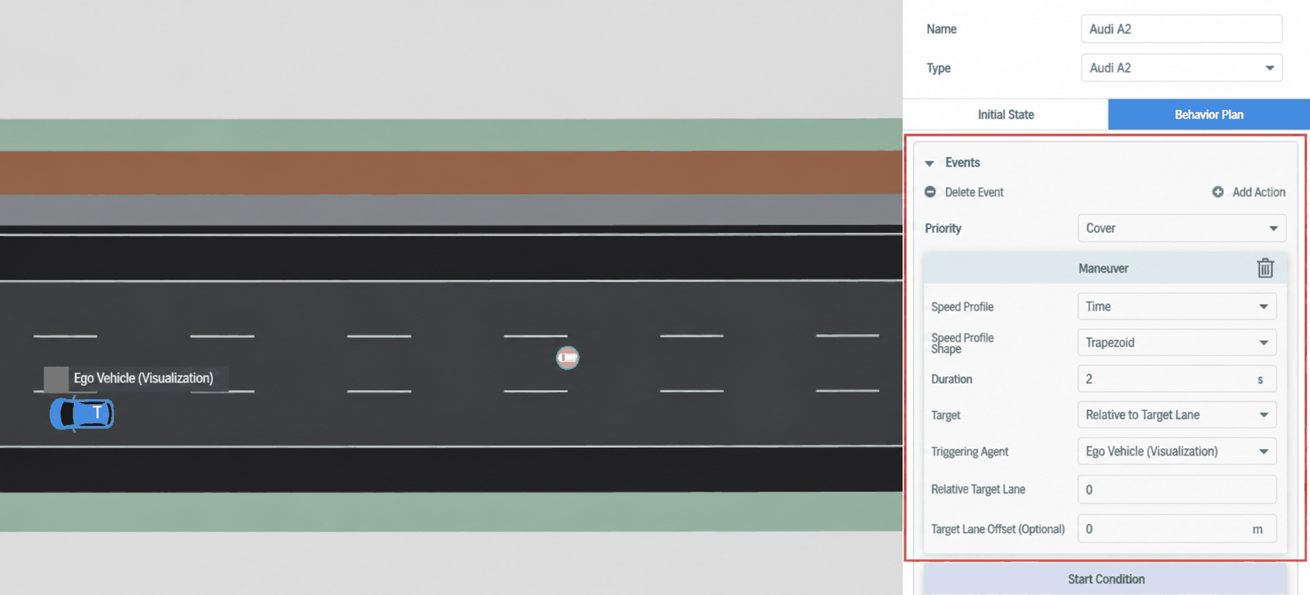
This tutorial map follows left-hand traffic rules — vehicles travel on the left side. Left-side lane IDs are negative; right-side lane IDs are positive.
2.4 Adding a Trigger
What is a trigger? It defines the timing or condition under which the AudiA2 performs its lane-change action.
In the action panel, click Start Condition → Add Condition and select the Relative Distance trigger. The lane change is triggered when the AudiA2 passes the ego vehicle by 5 meters — the AudiA2 is both the trigger actor and the triggered object.
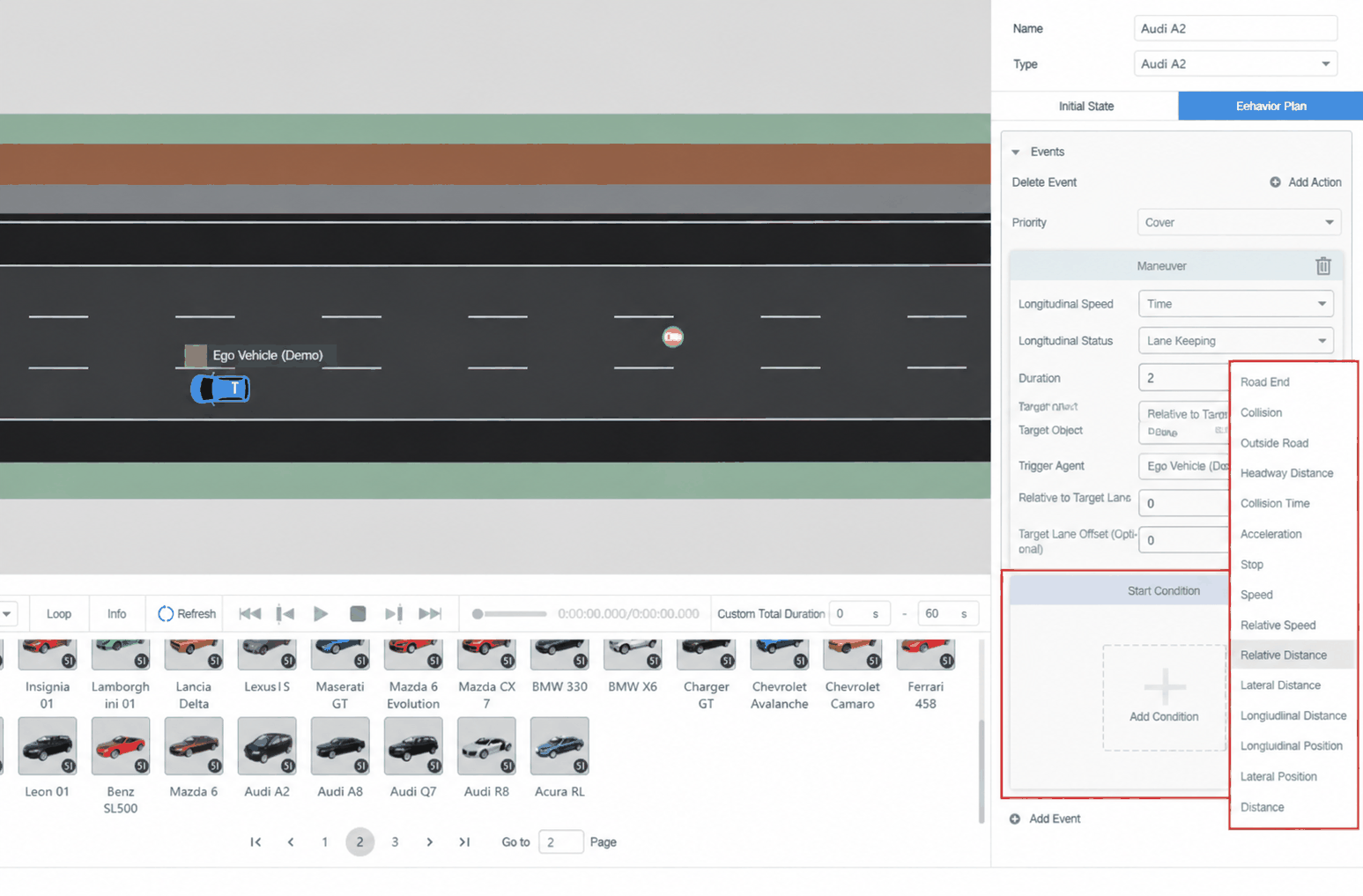
Adjust the parameters as follows; leave the rest at default:
- Reference Object: Ego Vehicle (Demo)
- Rule: >
- Relative Distance: 5 m
- Condition Edge: Rising
Rising means the condition triggers when it changes from False to True. At the start of the test, the distance between A2 and the ego vehicle is less than 5 m (False). As A2 overtakes and the distance exceeds 5 m, the condition becomes True and the trigger fires.
Under Trigger Actor Management → Add Trigger Actor, set the actor to AudiA2.
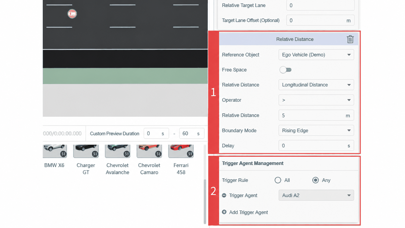
Condition Edge Options
- Rising: Triggers when the condition transitions from False to True.
- Falling: Triggers when the condition transitions from True to False.
- Rising or Falling: Triggers on either transition.
2.5 Previewing the Lane Change
After configuring the scenario, use the preview to verify it behaves as expected. (During preview, the ego vehicle, NPC vehicles, and other dynamic elements are driven by the SimOne engine — no algorithm, dynamics, or evaluation logic is involved.)
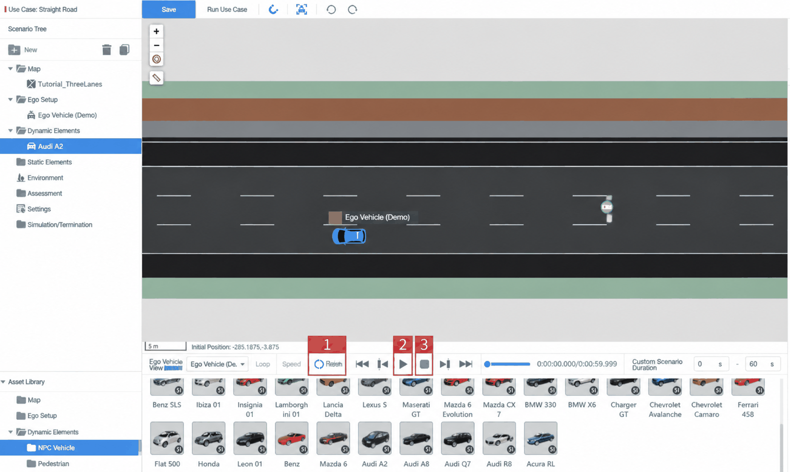
- Click the Refresh preview button (label 1). Once the timeline turns from gray to blue, click Play (label 2) to enter preview mode. You should see the AudiA2 gradually approach the ego vehicle, pass it, and then begin the lane change. The first lane-change event is set up correctly.
- In preview mode, the viewport follows the ego vehicle and all objects in the map are unselectable. Click Stop (label 3) to exit preview mode and return to edit mode.
3. Setting Evaluation Conditions and Running the Task
3.1 Adding Evaluations
SimOne automatically adds Collision and Timeout evaluations to every case. The Case Resource Library → Evaluations folder contains additional evaluation types that can be added as needed.
3.2 Setting the Case End Trigger
The Case End Trigger terminates the test when a specified condition (or group of conditions) becomes True. Every test case must have an end trigger. SimOne adds a default End Trigger to new cases with the condition: simulation time > 60 s — meaning the test automatically ends when 60 s has elapsed and no evaluation has triggered a case failure. Users can customize this.
Navigate to the Case End Trigger settings page. Click Condition Group → Simulation Time and adjust the value. The default is 60 s; for this tutorial, change it to 15 s since the route is short and a collision is likely sooner.
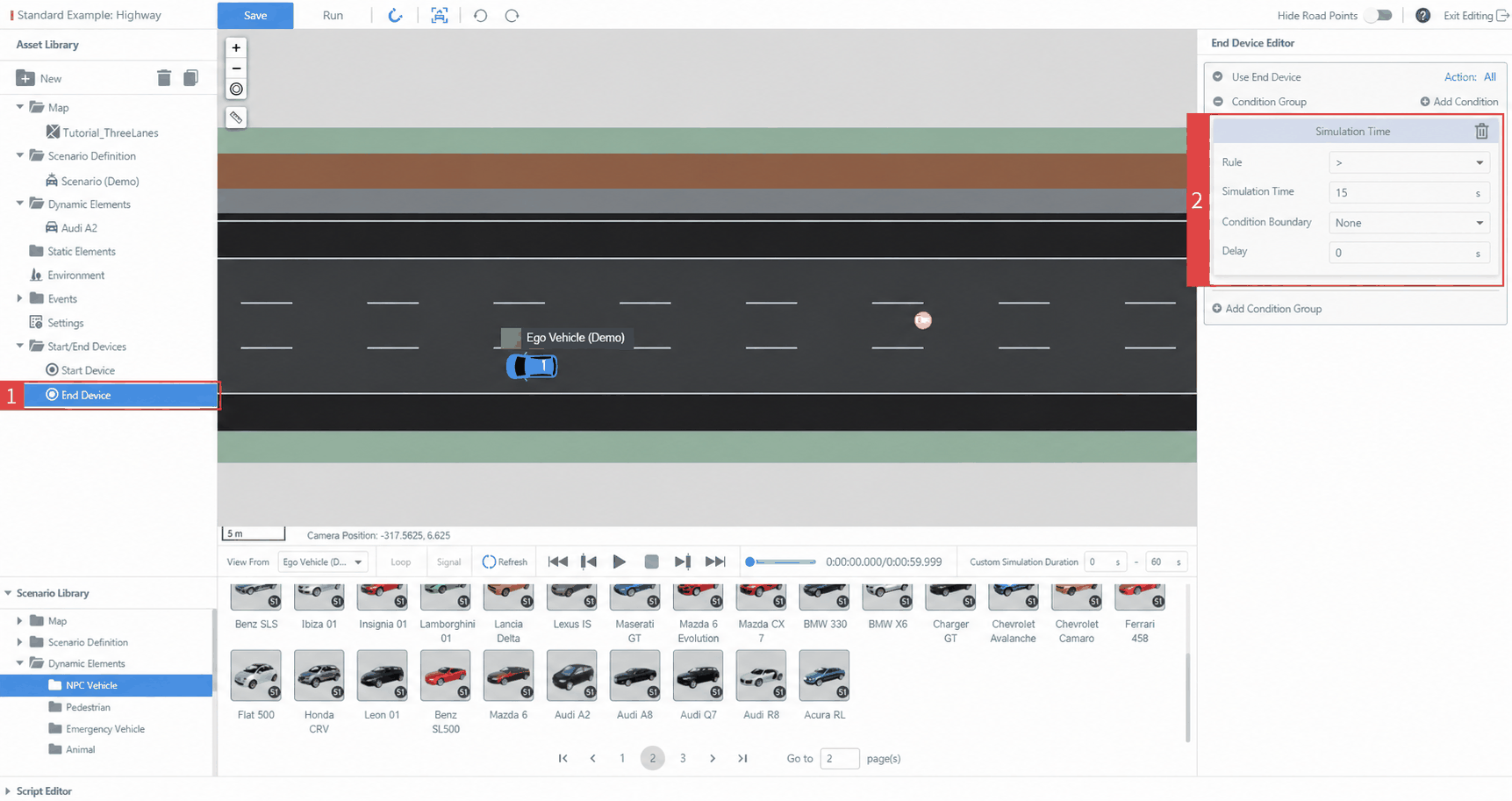
Parameters:
Rule: >
Simulation Time: 15 s
Condition Edge: None
Delay: 0 s
After setting the end trigger, click Refresh and then Play to run the case.
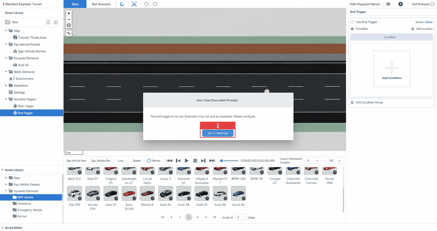
When no end trigger is set, the following actions will prompt the editor to remind you:
- Clicking the Refresh button.
- Clicking Run Case.
- For example — clicking Run Case: the system will display a prompt asking you to set an End Trigger. Click Go to Settings.
3.3 Running the Case
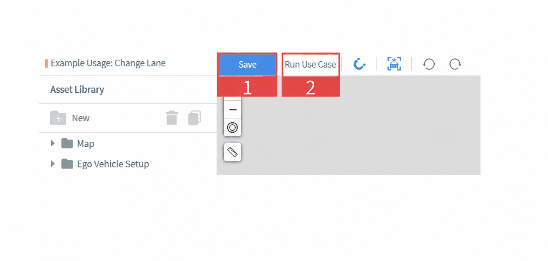
- Click the Save button in the top toolbar. When the Save button turns gray, the case has been saved successfully. Click Run Case to open the New Task window, where you can replace the ego vehicle configuration with one connected to an algorithm.
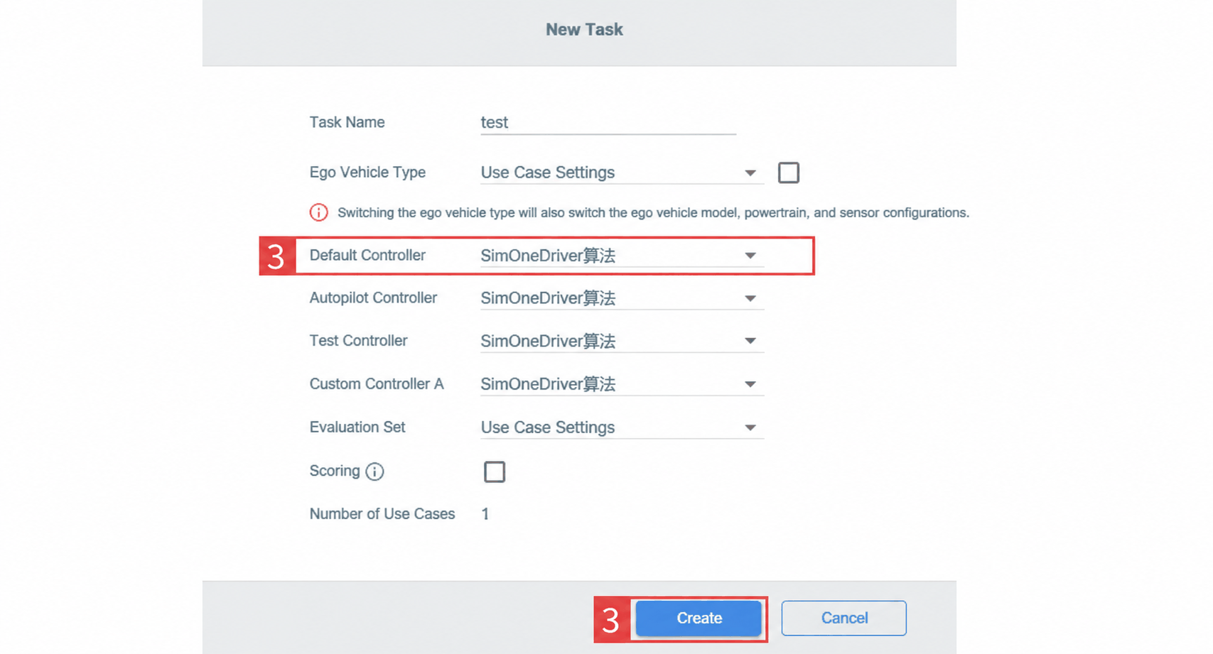
- If the controller set in step 1.2 is the default controller, you only need to change the algorithm — for example, set it to the
SimOneDriveralgorithm. Click Create and the system will automatically add the test task.
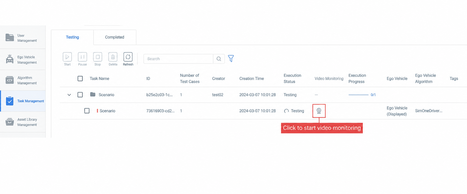
After clicking Run Case here, exit the editor by clicking Exit Editor (top-right corner) and go to the Task Management section on the SimOne main page to view test progress and results.
4. Observing the Test
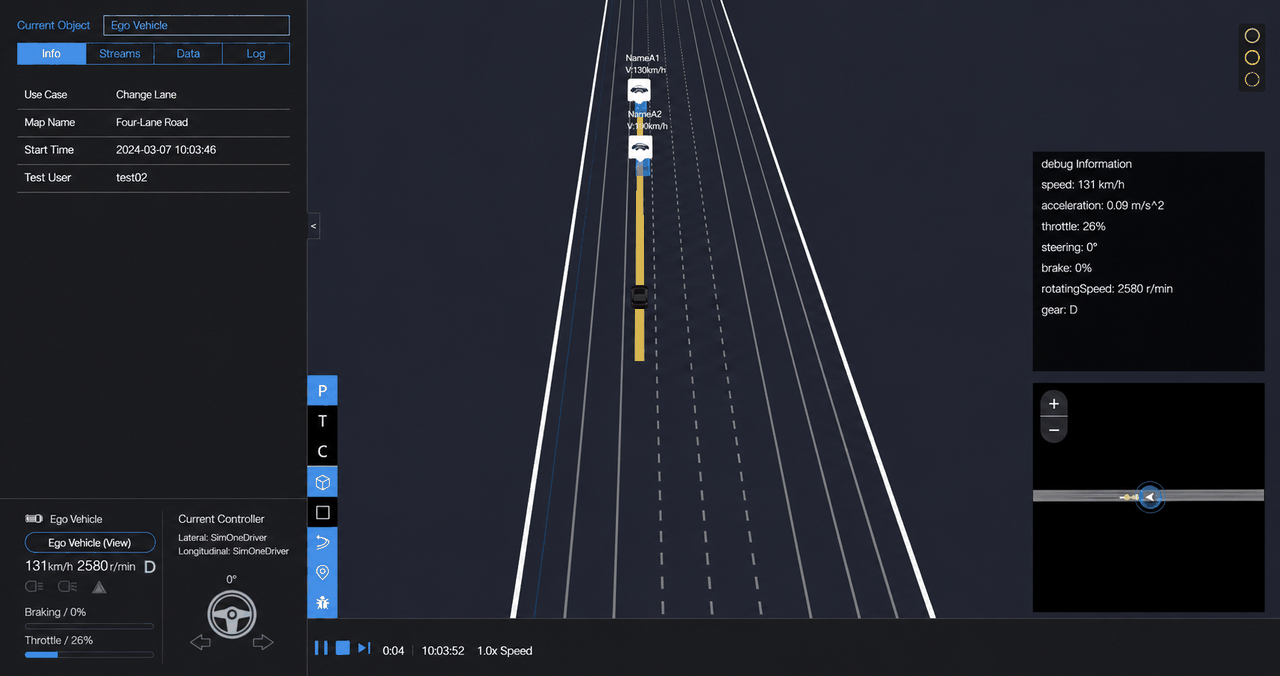
A visualization window will pop up automatically. See the Task Management page for details.
Appendix — Route Editing Steps
SimOne provides three ways to define the motion route of a dynamic object:
- Route (AssignRouteAction) based on Road Network: A route generated using at least two waypoints and a route planning strategy.
- Acquire Position (AcquirePositionAction): The target position the dynamic object must reach from its current location, using the road network and a shortest-path strategy.
- Follow Trajectory (FollowTrajectoryAction): Defines the motion trajectory of a dynamic object using a fitted curve.
1. Creating a Route
Based on the road network, using at least two waypoints and a route planning strategy.
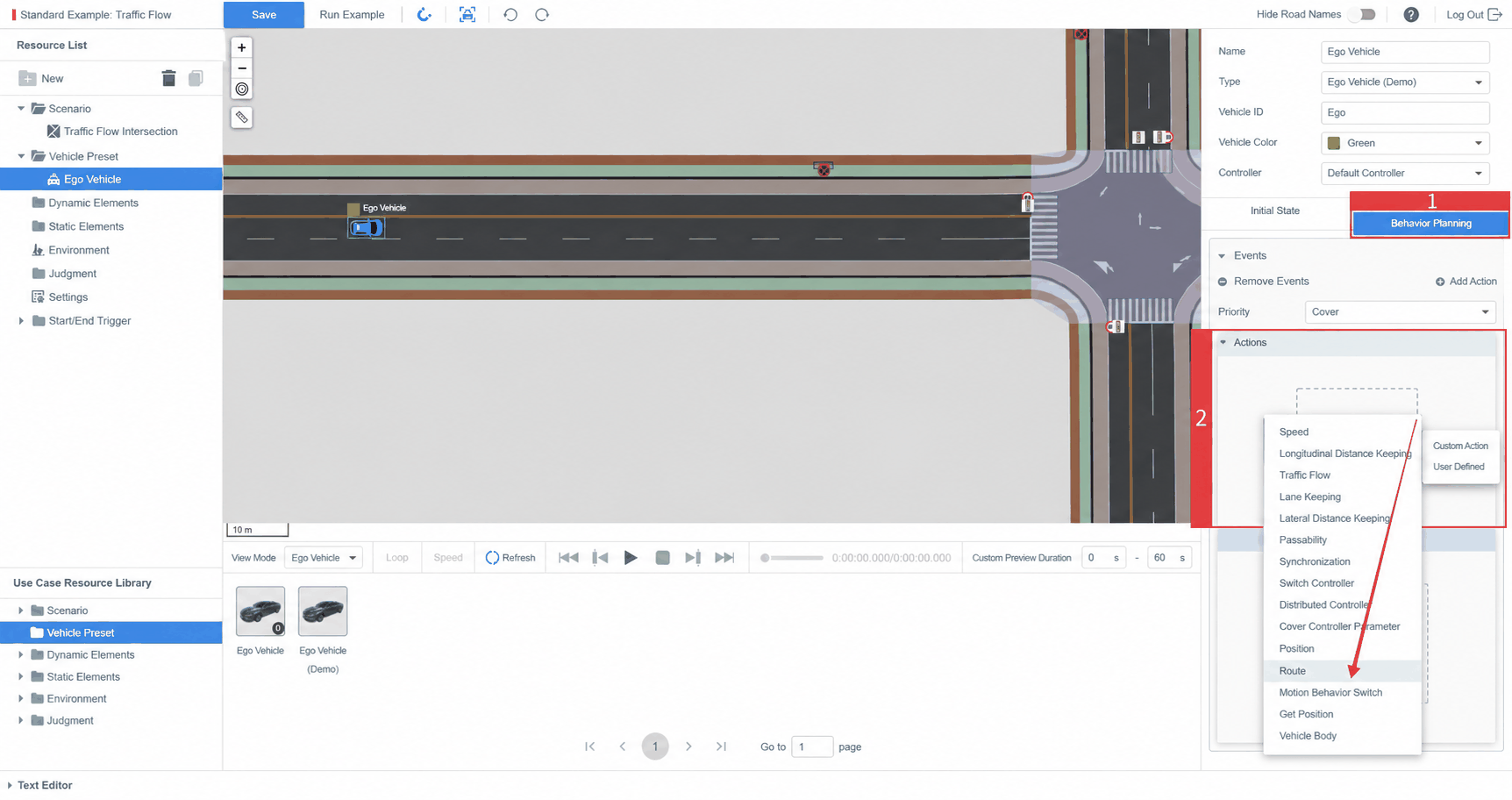
- Select the ego vehicle in the viewport, then click the Behavior Planning panel on the right. Click Add Event → Action → Add Action → Private Action → Route.
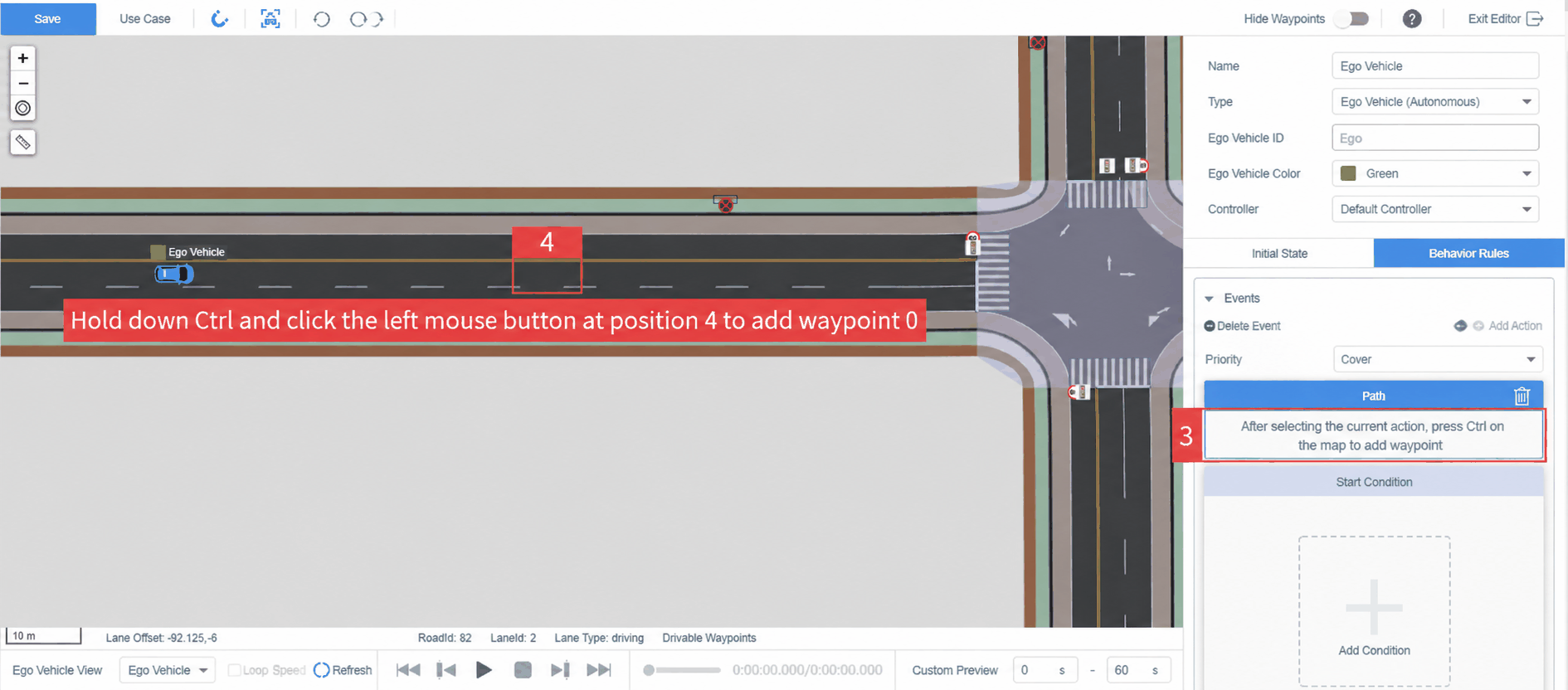
- Following the prompt, hold Ctrl and click the starting position shown in the diagram to add Waypoint 0.
Waypoint 0 coordinates are shown in the figure.
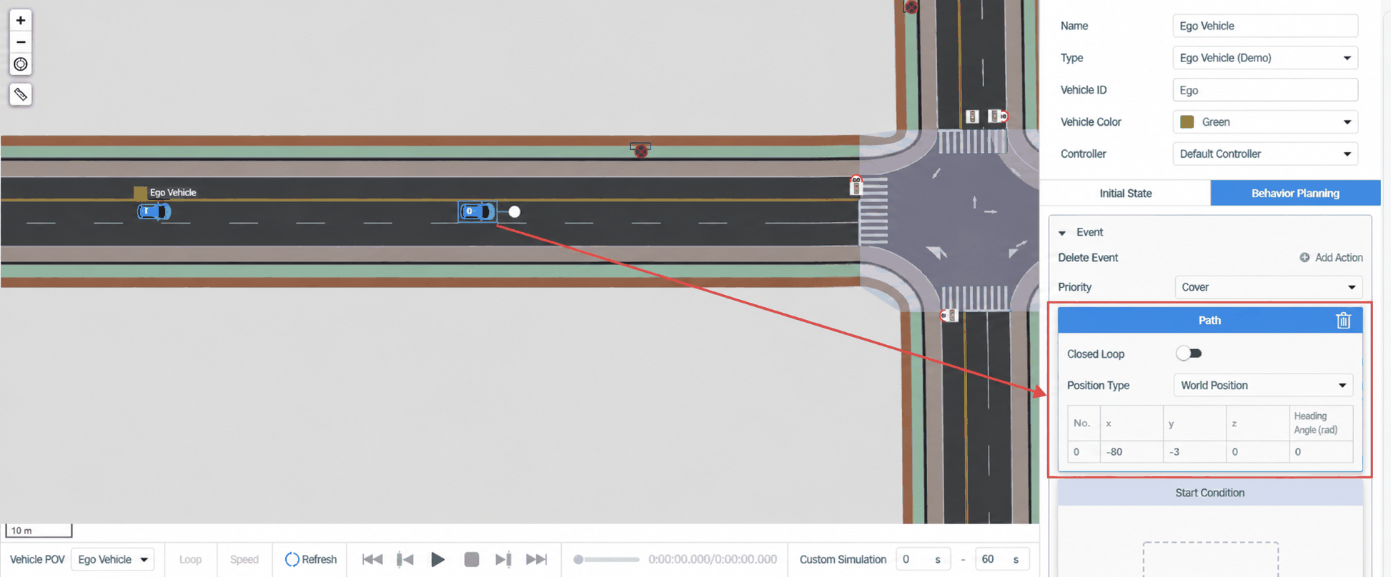
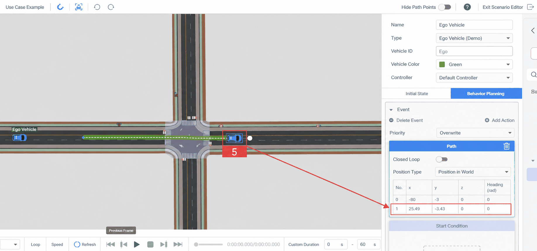
- Hold Ctrl again and click the next position to add Waypoint 1, then release Ctrl. A green path line connects Waypoint 0 and Waypoint 1, reflecting the road-network-based route planning result.
This result is for reference only. During the actual test, the ego vehicle's path depends on the user's planning algorithm.
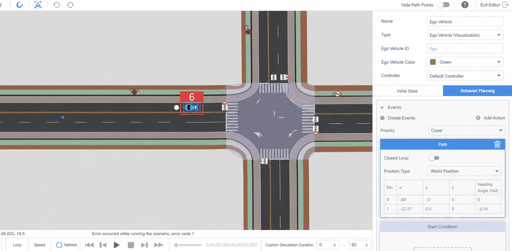
- Select Waypoint 1 and drag it to the opposing adjacent lane (label 6) opposite Waypoint 0's lane. After releasing, the green path line disappears — indicating that the ego vehicle may not be able to drive from Waypoint 0 to Waypoint 1 in the actual test.
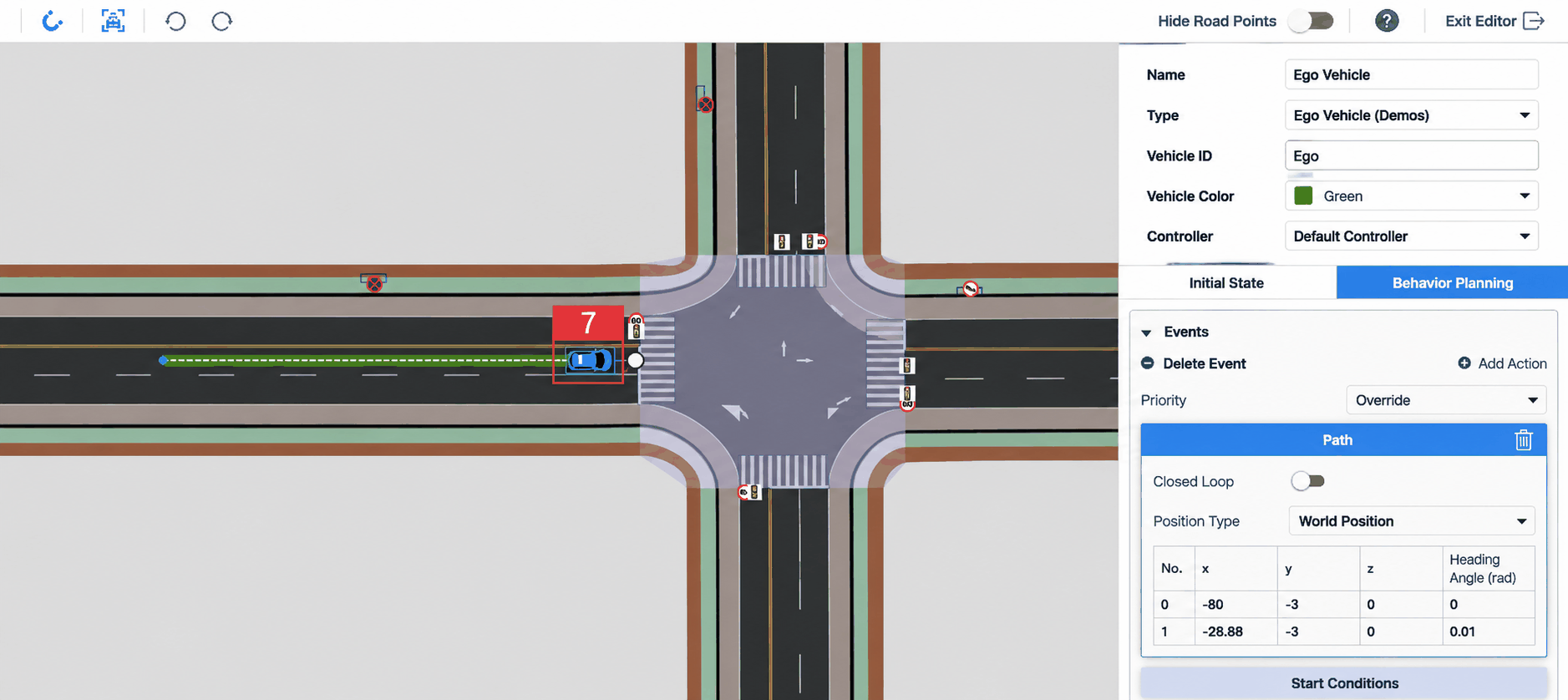
- Continue dragging the waypoint back to the same lane as Waypoint 0 (label 7). The green path line reappears, confirming successful route planning.
- The route is now complete. The steps for creating a route are the same for all dynamic objects.
Remember to click Refresh after configuring the route to preview the latest result.
Select a waypoint and press Delete to remove it.
Select a waypoint and press Ctrl to insert a new point after the selected one.
A minimum of two waypoints is required; there is no upper limit. Add as many as needed.
2. Creating an Acquire Position Action
Acquire Position causes the dynamic object to travel from its current position to a target location using the road network and a shortest-path strategy.
2.1 Setting the Initial Position
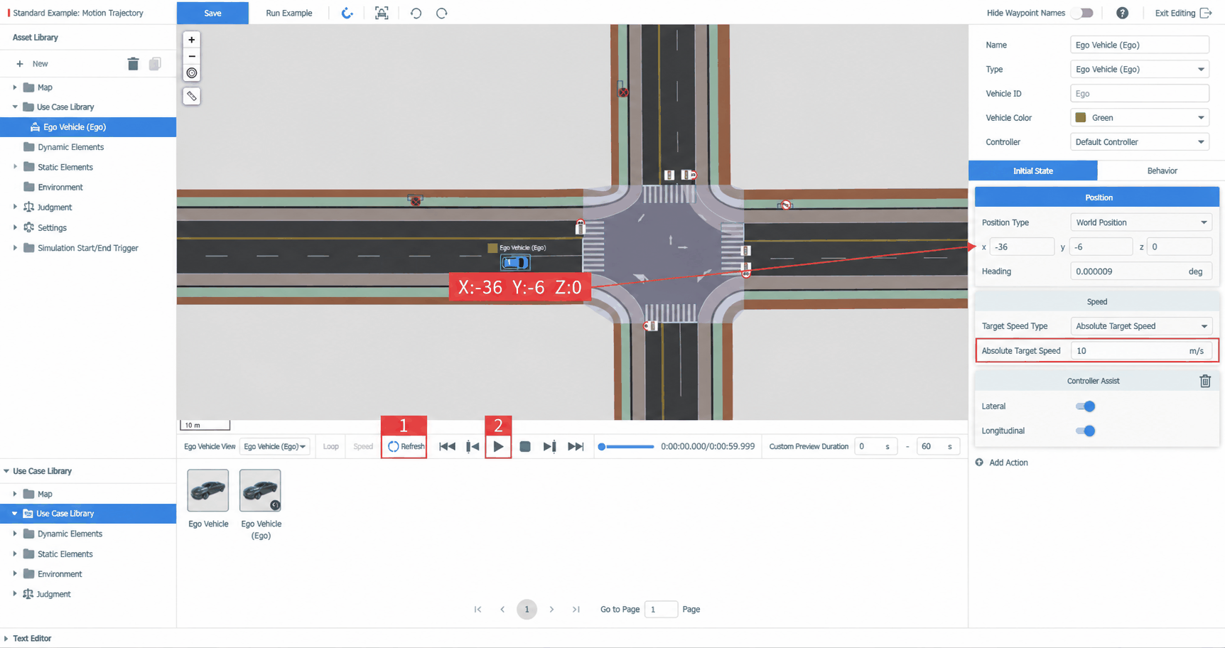
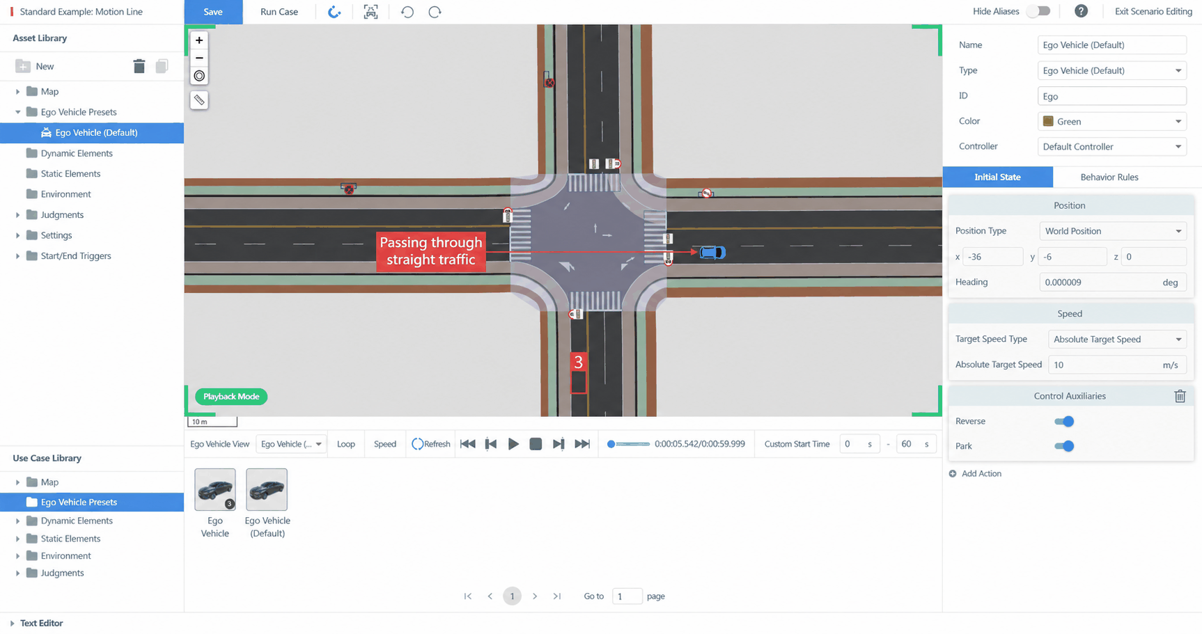
- Select the ego vehicle in the viewport and set its initial position to X: -36, Y: -6, Z: 0.
- Click Refresh (label 1) and then Play (label 2) — the ego vehicle drives straight through the intersection.
- Now we will specify that the ego vehicle should turn right at the intersection and reach position (label 3).
2.2 Adding the Acquire Position Action
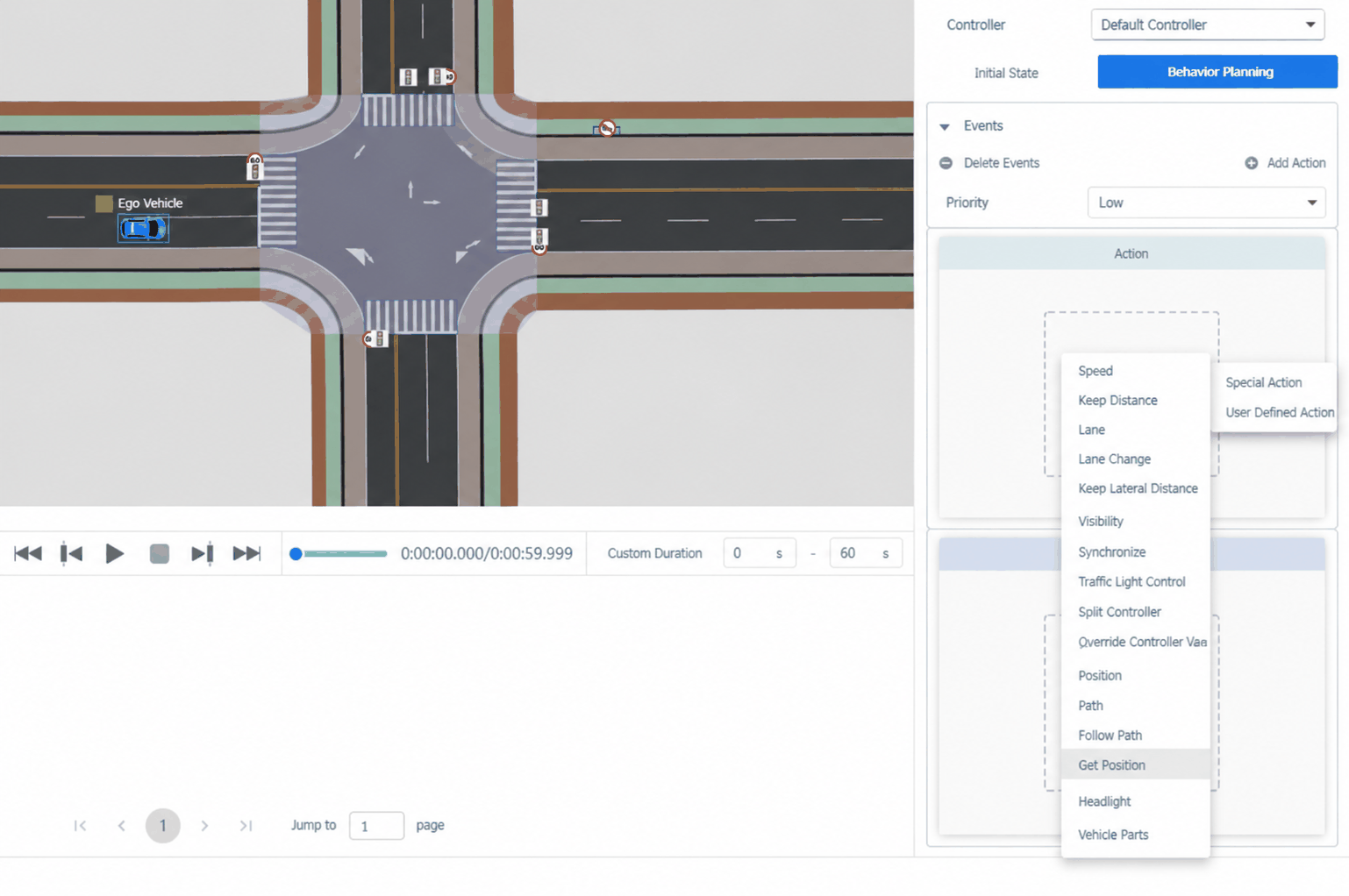
- Press Esc to exit playback mode. Click the Behavior Planning panel, then add Private Action → Acquire Position.
- Following the prompt, hold Ctrl and click the target position at X: -7, Y: -40, Z: 0 to add the position point.
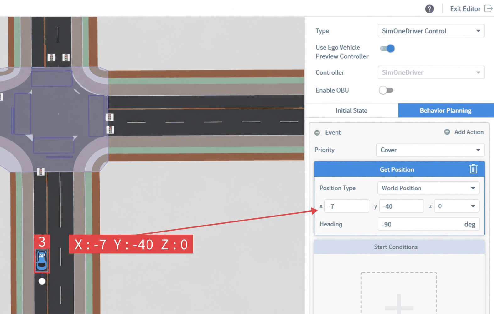
- Acquire Position requires only one position point. The test vehicle will use the shortest-path strategy to reach it.
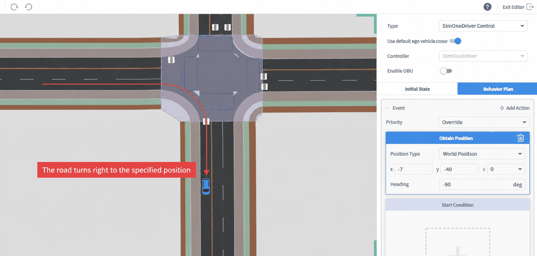
- Click Refresh again, then Play — the ego vehicle will turn right at the intersection and arrive at the specified position.
3. Creating a Follow Trajectory Action
Follow Trajectory uses a fitted curve to define the dynamic object's motion path.
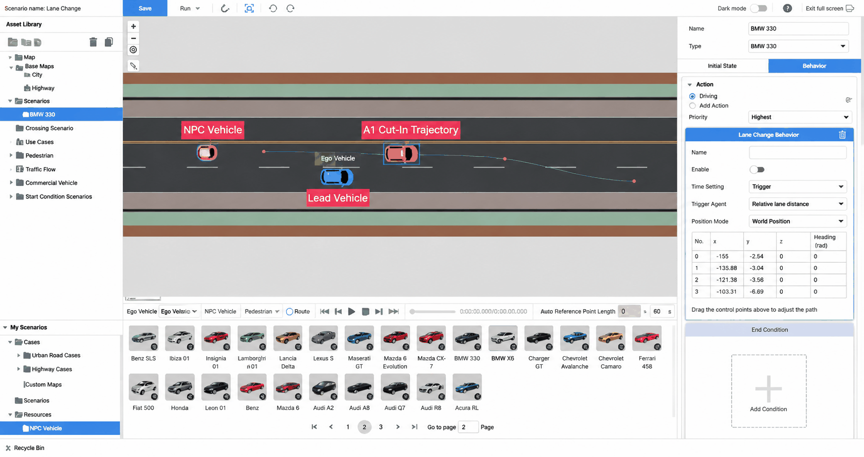
The following demonstrates how to use Follow Trajectory to create a lane-change cut-in maneuver where the NPC vehicle cuts into the ego vehicle's lane — useful for reproducing hazardous driving scenarios.
3.1 Adding an NPC Vehicle and Setting Coordinates and Speed
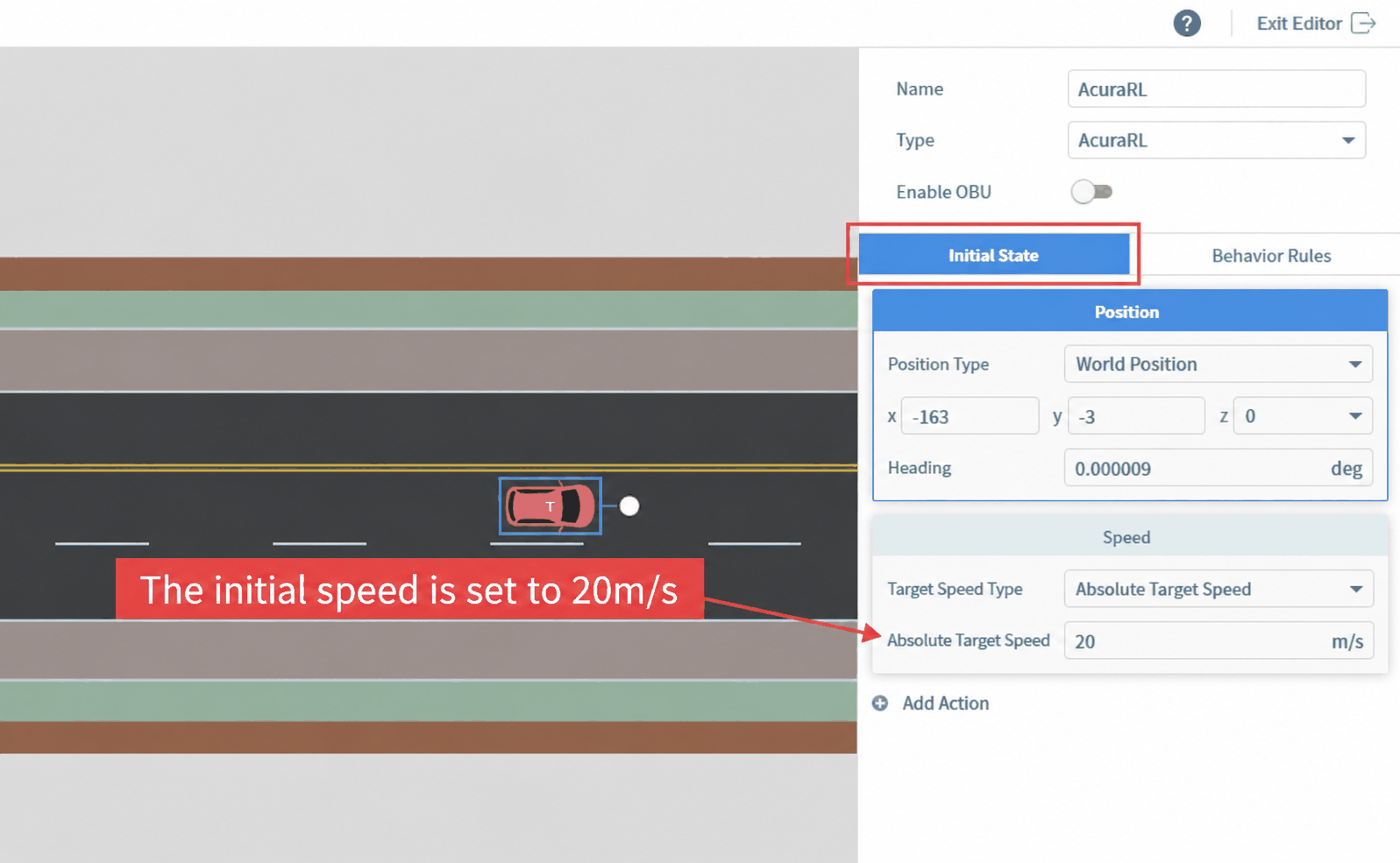
- From Case Resource Library → Dynamic Elements → Standard NPC Vehicles, drag any NPC vehicle into the viewport. Set its coordinates to X: -163, Y: -3, Z: 0. Set the ego vehicle's coordinates to X: -145, Y: -6, Z: 0.
- Set the NPC vehicle's initial speed to 20, or any value higher than the SimOneDriver's initial speed.
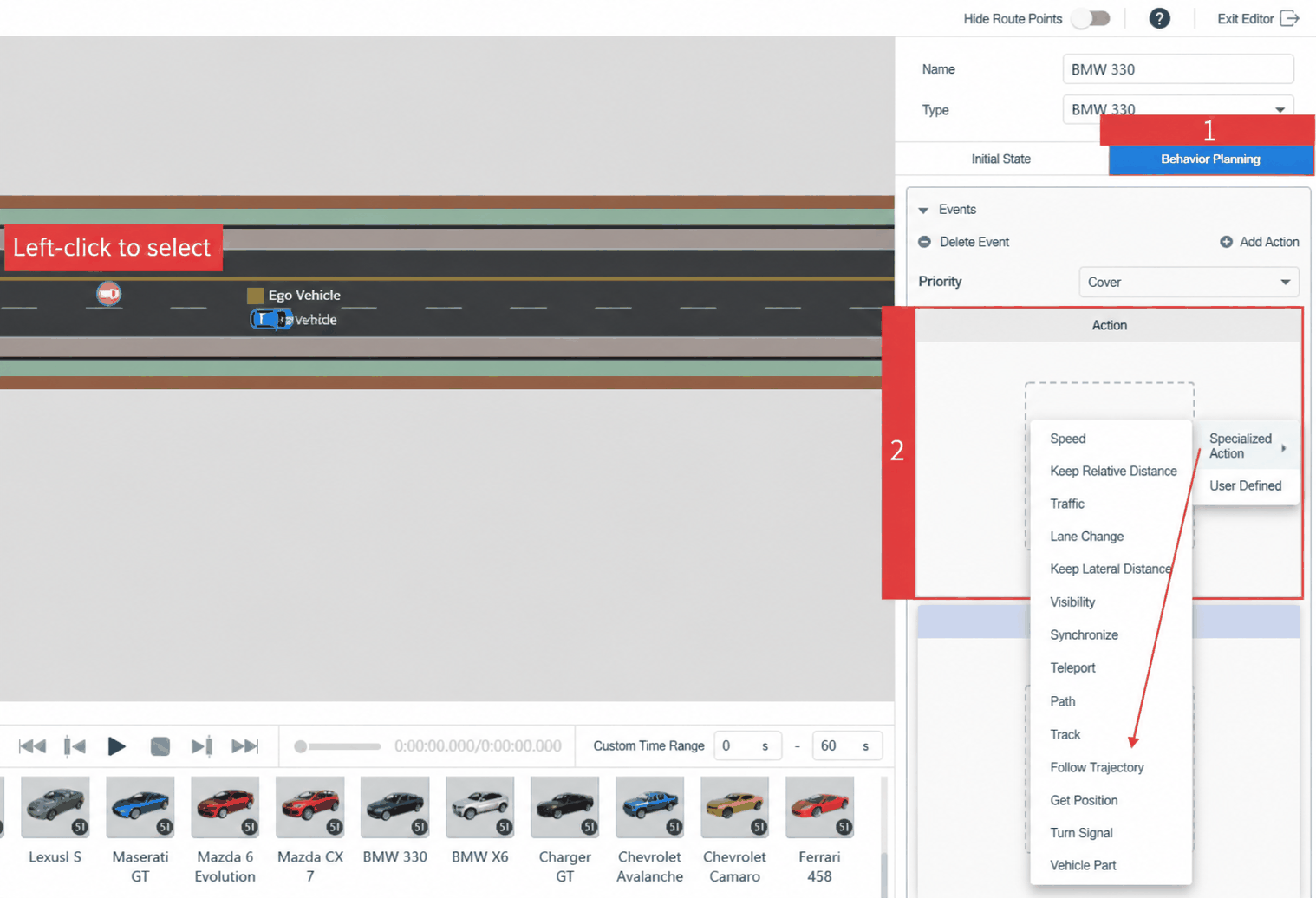
- Select the NPC vehicle in the viewport. In the Behavior Planning panel, add Private Action → Follow Trajectory.
- Following the prompt, hold Ctrl and click the position behind and to the left of the ego vehicle to add Trajectory Point 0 at approximately X: -150, Y: -3, Z: 0. Exact placement is not critical — just ensure the point is behind and to the left of the ego vehicle.
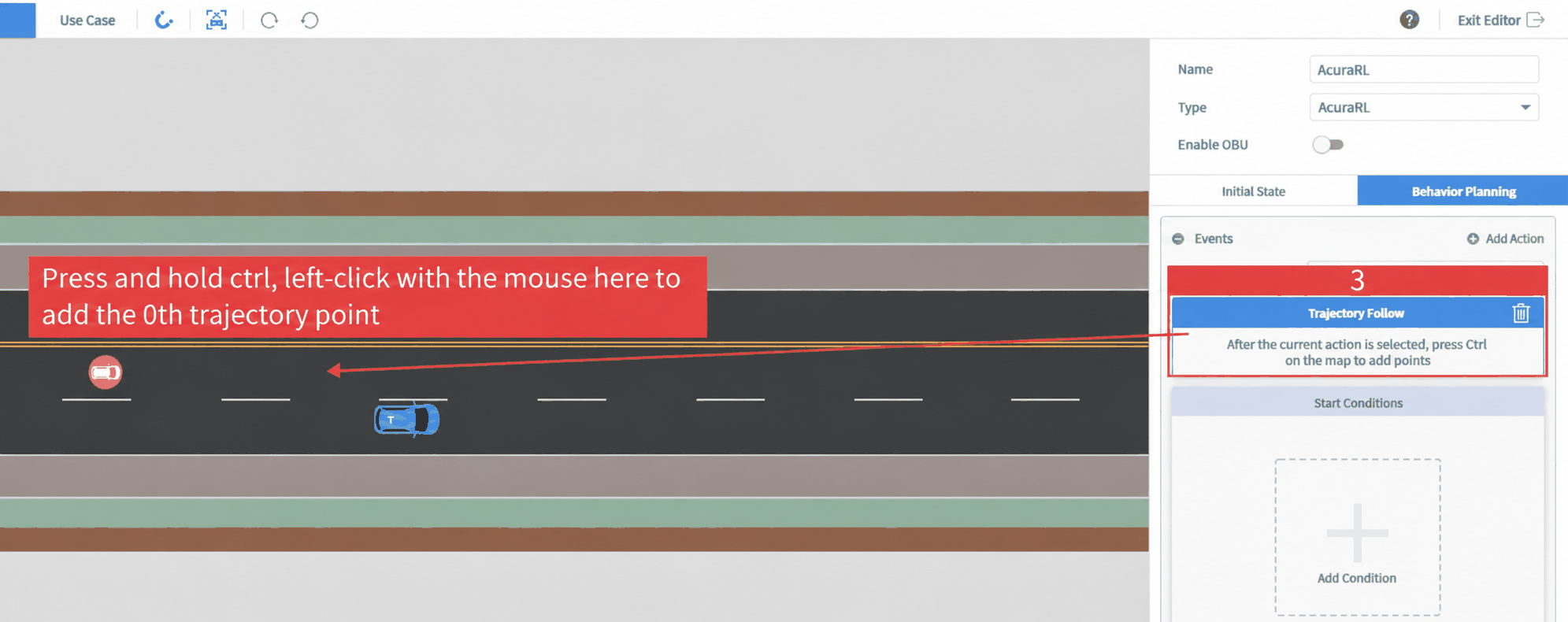
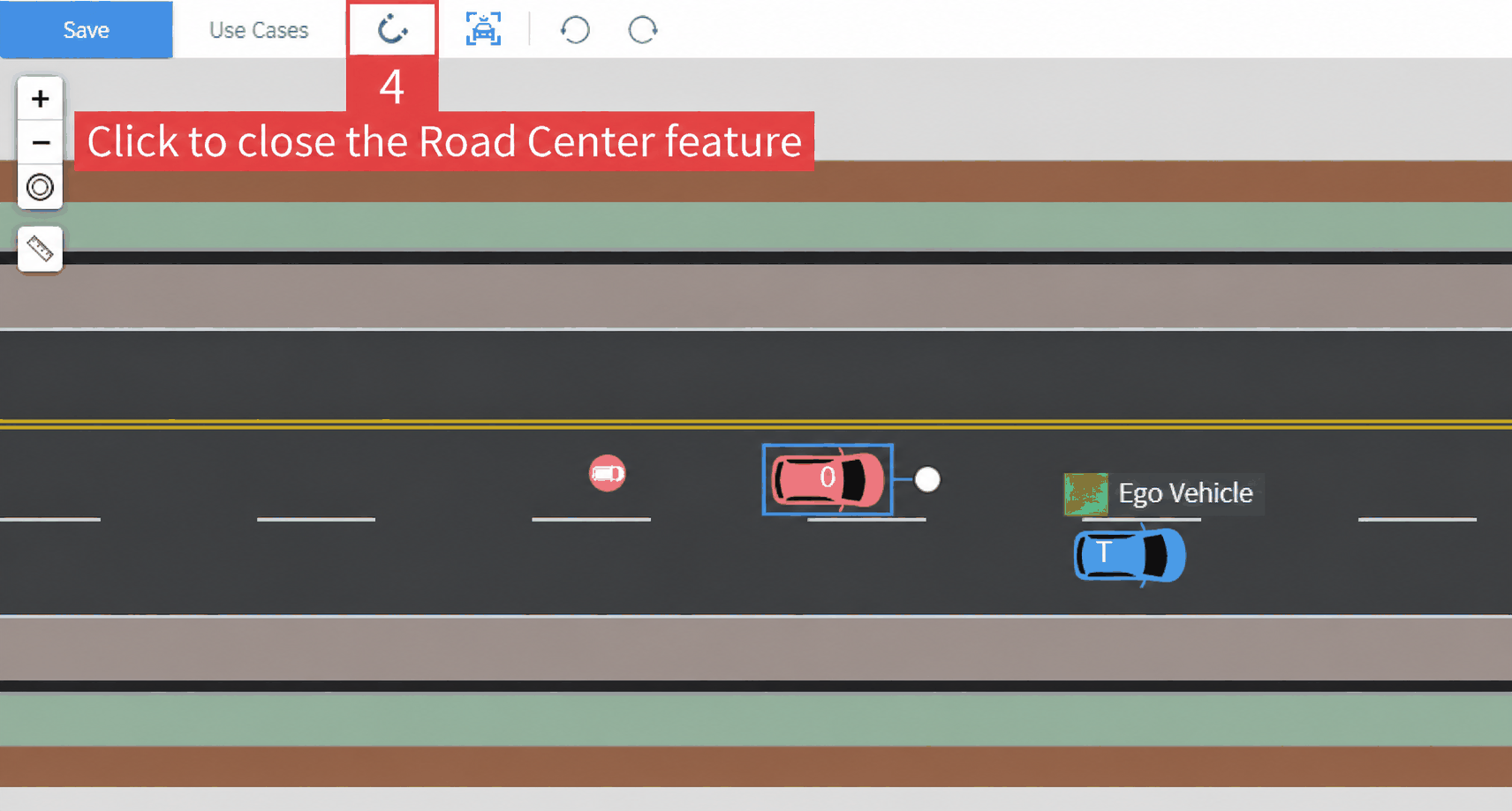
- Click to disable the Snap to Lane Center feature so trajectory points can be placed more freely.
- Hold Ctrl again and click sequentially at labels 5, 6, and 7 to add Trajectory Points 1, 2, and 3. Coordinates are shown in the figure — these are for reference; relative positioning is what matters.
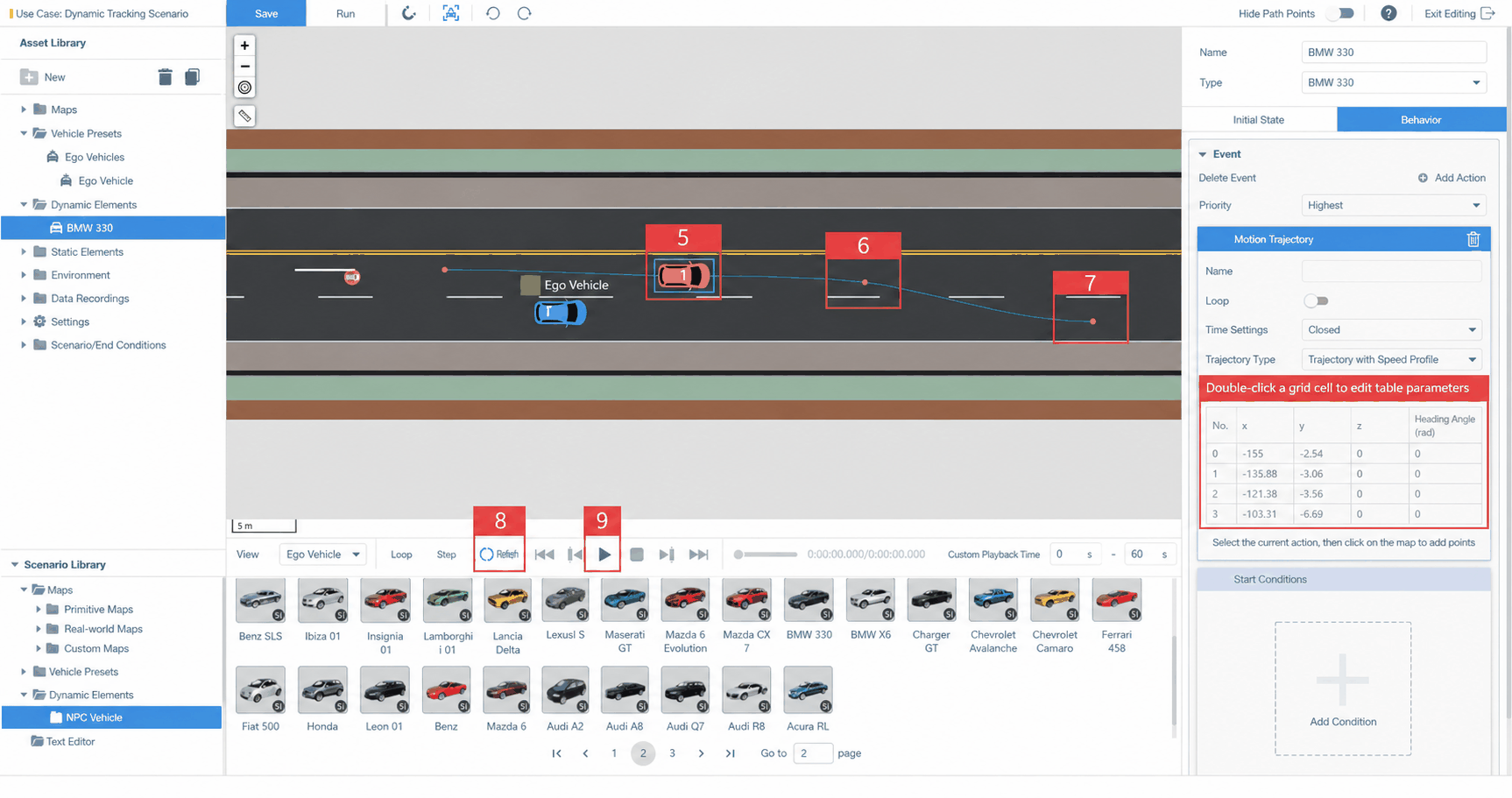
- By adding 4 trajectory points, you have created a lane-change trajectory. The vehicle will follow this trajectory.
- Click Refresh, then Play — the NPC vehicle will perform the lane-change cut-in maneuver along the defined trajectory.