Ego Vehicle Management
To train and test algorithms, users must select and configure ego vehicle resources in advance. Once configured, the appropriate ego vehicle can be selected when editing test cases.
Chapter Contents
| Section | Description |
|---|---|
| 4.2.1 Select / Import Model | Select a built-in model or import a UE-packaged ego vehicle model |
| 4.2.2 Configure Sensor Devices | Configure object-level and physical-level sensors, as well as V2X devices |
| 4.2.3 Configure Dynamics | Configure built-in dynamics and third-party dynamics (MIL only) |
| 4.2.4 Configure Rendering Viewport | Configure the ego vehicle's rendering viewport (DIL only) |
Ego Vehicle Editor Interface
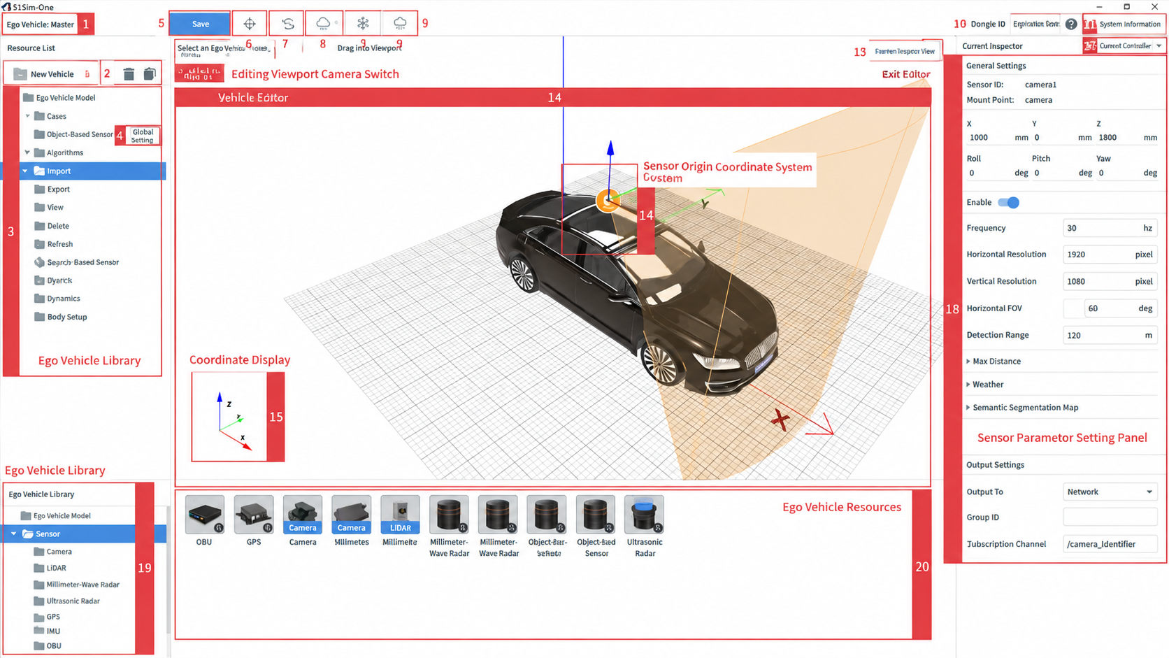
| ID | Item | Description |
|---|---|---|
| 1 | Ego Vehicle Configuration Name | Displays the name of the ego vehicle being edited |
| 2 | Delete / Copy Button | Delete or copy items in the resource list on the left side of the Ego Vehicle Editor |
| 3 | Ego Vehicle Resource Tree | Displays the resources added to the ego vehicle in the left-side resource list tree |
| 4 | Add Sensor Fusion Group | Click to add a new sensor fusion group |
| 5 | Save | After completing the ego vehicle configuration, click this button to save all resources |
| 6 | Cartesian Coordinate System | When the translation coordinate system is selected, sensors in the editor can be moved along the X, Y, and Z axes. This is the default mode. |
| 7 | Rotation Coordinate System | When the rotation coordinate system is selected, sensors in the editor can be rotated accordingly. Users can switch between the rotation and Cartesian coordinate systems. |
| 8 | Undo | Undo to the previous step |
| 9 | Redo | Redo to the next step |
| 10 | Help Center | Click to open the Help Center documentation |
| 11 | Exit Editor | Click to close the Ego Vehicle Editor dialog |
| 12 | Viewport View Toggle | Switch the editing viewport angle, including perspective, top, left, right, front, and rear views |
| 13 | Preview Detection Range | Click to open a preview panel on the right showing the detection range of the configured sensors |
| 14 | Sensor Origin Coordinate System | Marks the origin of the sensor's 3D coordinate system; sensor rotation is centered on this origin |
| 15 | Cartesian Axis Display | Shows the X, Y, Z axis directions |
| 16 | Save Sensor Parameters | Save the parameters of sensors dragged into the editor so they can be reused directly next time without re-configuration |
| 17 | Restore Defaults | Click to restore all sensor parameters to their default values |
| 18 | Sensor Parameter Panel | Modify sensor parameters in this panel |
| 19 | Ego Vehicle Resource Library List | Click an entry in the left resource list to display its resources on the right; drag resources into the editor |
| 20 | Ego Vehicle Resource Display | Click a folder in the resource library list to display the ego vehicle models it contains on the right |
The ego vehicle configuration primarily includes model selection, sensor configuration, dynamics configuration, and rendering viewport configuration. See the sections below for details.
1. Create an Ego Vehicle
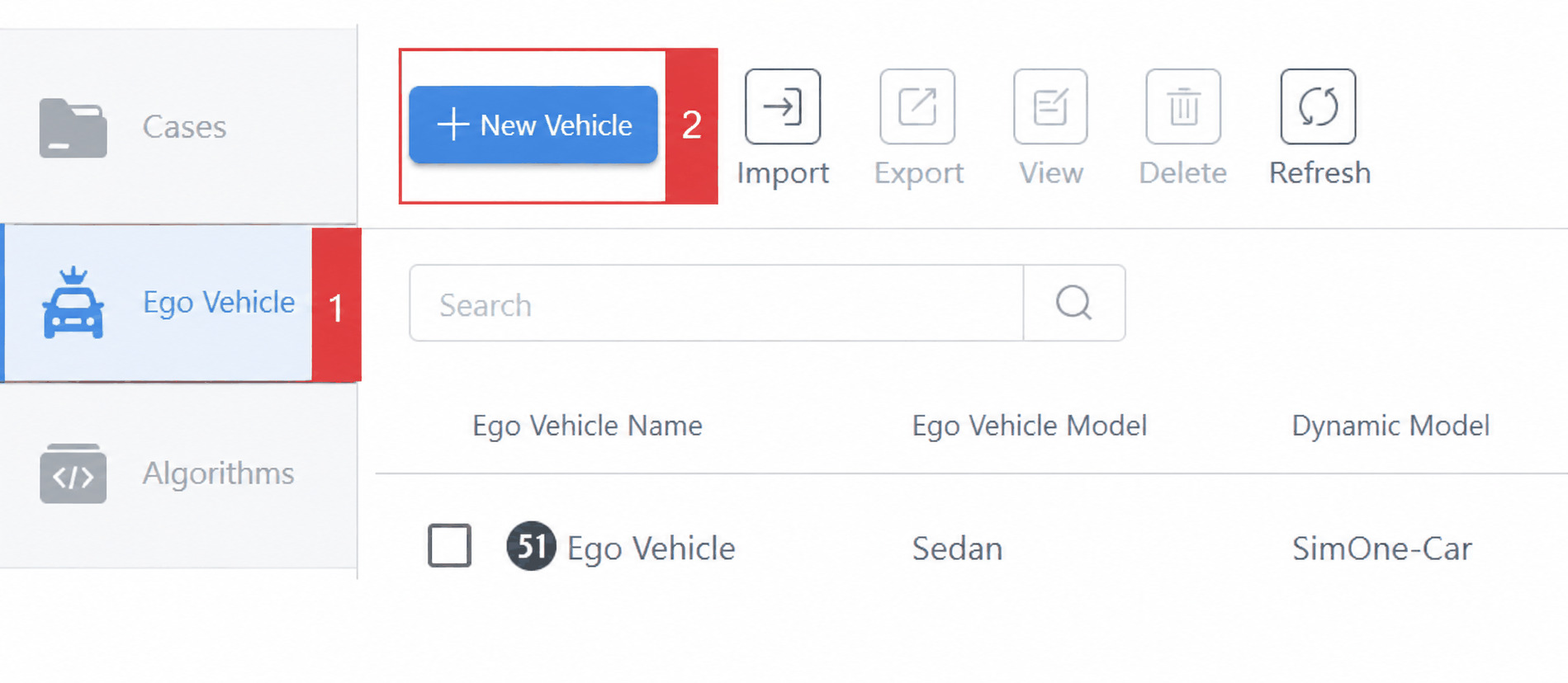
Go to the Ego Vehicle page and click the Create Ego Vehicle button to enter the Ego Vehicle Editor.
2. Ego Vehicle Editing Viewport
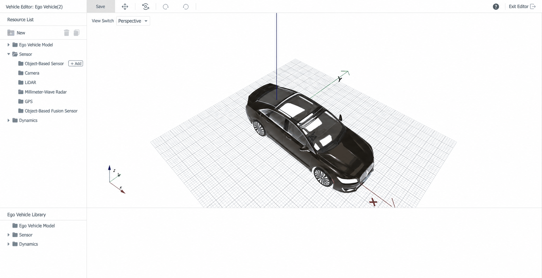
When a new ego vehicle is created, the Ego Vehicle Editing Viewport opens automatically so you can start editing right away.
3. Configure Ego Vehicle Model
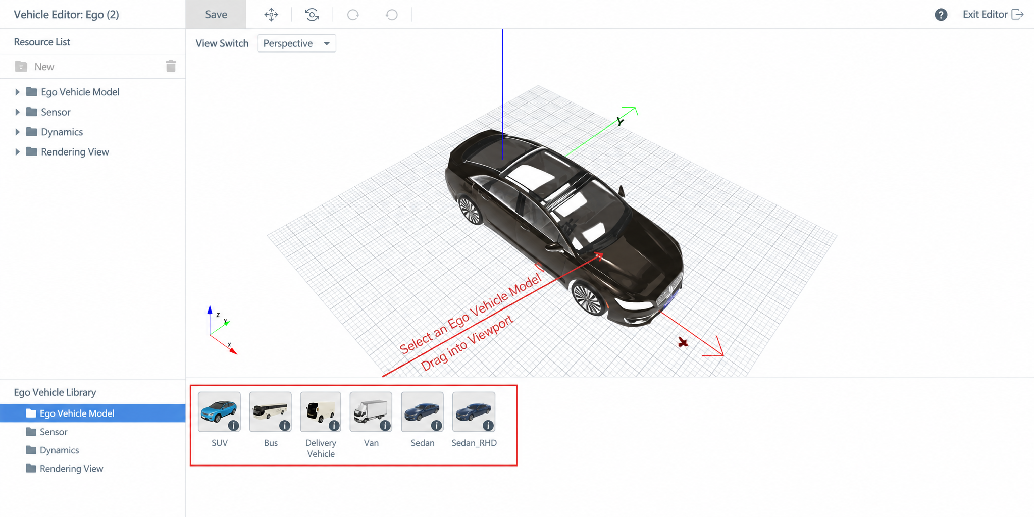
Select an Ego Vehicle Model. You can also import a custom (plug-in) model. See Select / Import Model (Built-in / UE-Packaged Import) for details.
4. Configure Sensor Model
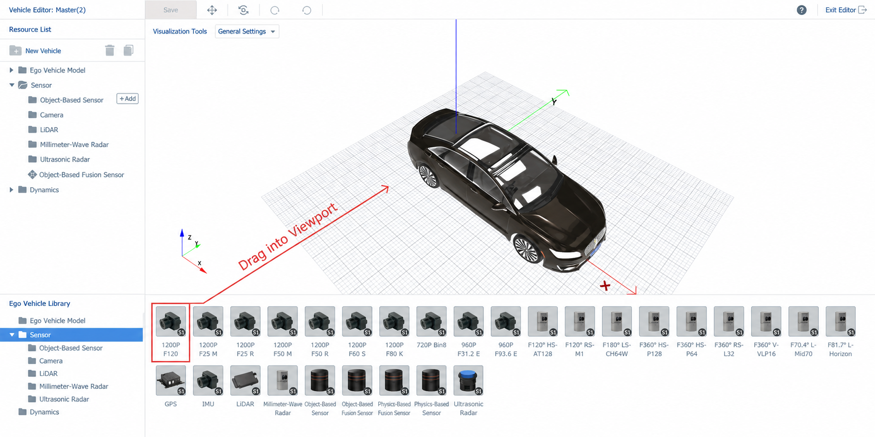
Drag and drop sensor simulation models from the Ego Vehicle Resource Library into the Ego Vehicle Editing Viewport. A single ego vehicle supports multiple sensors.
Tip
Currently supported sensors include Object-Level Sensors, Camera, LiDAR, Millimeter-Wave Radar (Standard / 4D), Positioning Sensor, and Ultrasonic Radar.
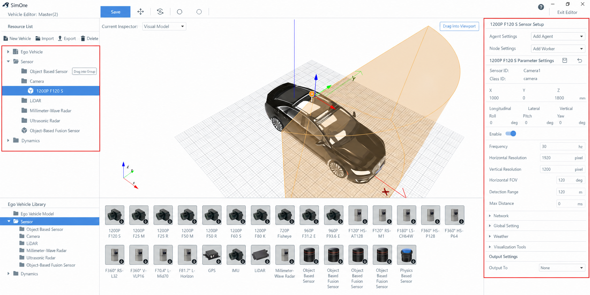
Select a sensor in the left Resource List to adjust its parameters in the Sensor Parameter Panel on the right.
For detailed parameter descriptions and usage (sensor fusion groups, data output settings), see: Configure Sensor Devices
5. Configure Ego Vehicle Dynamics
Drag and drop a dynamics model from the Ego Vehicle Resource Library into the Ego Vehicle Editing Viewport.
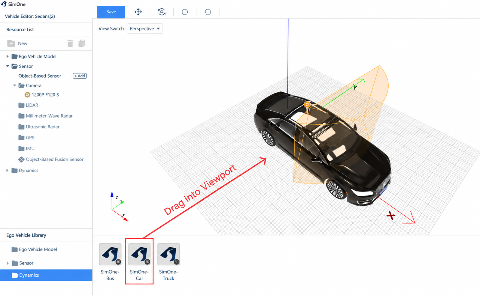
Supported dynamics models:
Tip
SimOne's own dynamics models include SimOne-Bus, SimOne-Car, and SimOne-Truck. Third-party dynamics systems CarMaker, CarSim, TruckSim, and VIGrade are also supported (not available on Collaboration Edition cloud).
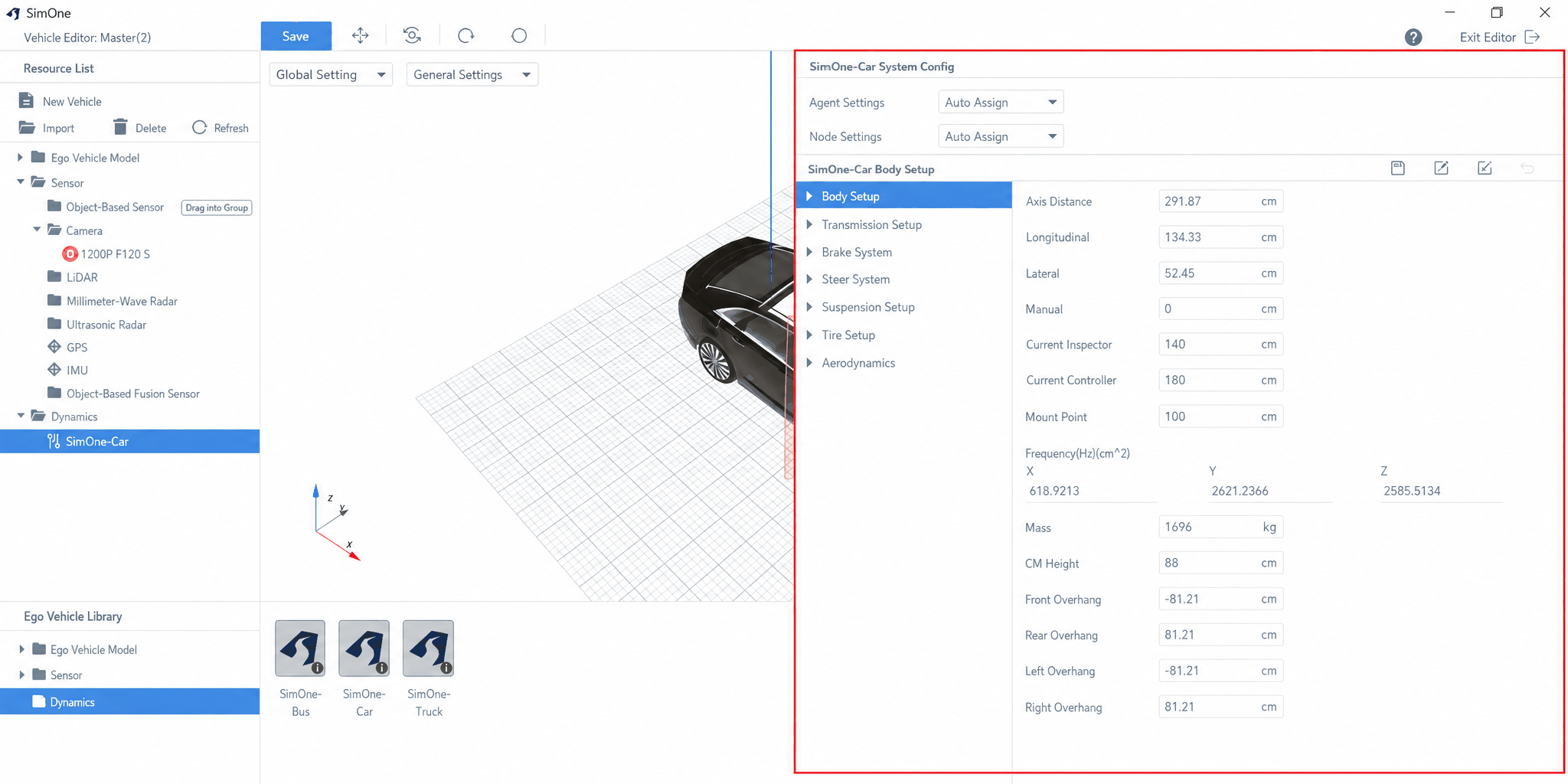
Configure the dynamics parameters in the parameter panel on the right.
For detailed parameter descriptions, see Dynamics Simulation Parameters
Tip
Click on an empty area in the Resource List to hide the Parameter Panel.
Save the configuration when done.
6. Configure Rendering Viewport (DIL Only)
For Driver-in-the-Loop (DIL) testing, a rendering viewport must be configured to drive the cockpit display.
See 7.3. DIL Driver-in-the-Loop Testing: Driving Mode Configuration