BEV Stitching Tool
3.3.1 Background
BEV (Bird's Eye View) technology provides a top-down view derived from sensor data for use in autonomous driving and other fields, enhancing environmental perception. BEV perception features occlusion handling, global field of view, and parallel multi-task execution. Its workflow includes data acquisition, preprocessing, and BEV perspective transformation. BEV imagery is widely used in autonomous driving for applications such as environmental perception, object detection, and path planning.
Before using BEV-perspective imagery for further applications, data annotation is required. Annotating real-world data often suffers from insufficient accuracy due to occlusions, lighting shadows, and limited scene diversity, as well as high time costs.
This tool, used in conjunction with SimOne, generates and stitches BEV data. A sample algorithm is provided to obtain BEV images and annotate parking space ground-truth information. The tool is included in the installation package and exposed to users at the path SimOne/Tools/BEVTools/.
3.3.2 Data Generation
This tool must be used together with SimOne to output simulation data.
Add fisheye cameras to the Ego Vehicle. If hardware capacity is limited, you can distribute the cameras across four Ego Vehicles — one camera per vehicle, each covering one direction — and then use a playback test case to generate fisheye camera data for all directions along the same route.
3.3.2.1 Fisheye Camera Setup
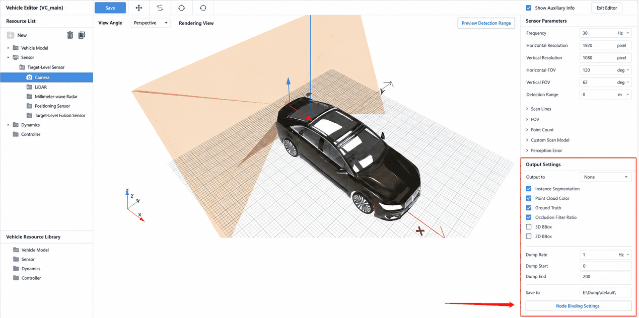
After adding multiple fisheye cameras, configure them as follows. Imaging settings can be adjusted as needed; the output settings must be changed as described:
(1)Click the dropdown in the Output to field and select Dump from the menu.
(2)In the new menu that appears, check RGB, Depth Map, and Lane Lines.
(3)Select the Dump frequency based on the simulation machine's hardware configuration.
(4)Dump Start and Dump End correspond to the start and end times for data dumping during the simulation run. Because there may be a brief wait when a test case starts, it is recommended to set the start time to 10 s to avoid excessive idle-state vehicle data in the Dump output.
(5)In the Save to field, enter the target path for the output data. After the test case runs, the Dump data will be saved to a new folder created at the specified path.
(6)Repeat the above steps to correctly configure each directional fisheye camera.
3.3.2.2 Recommended Dump Data Workflow
Due to variation in simulation machine hardware, the following is a generally applicable Dump data workflow.
(1)Prepare 5 Ego Vehicles — one without any fisheye camera, and the remaining four each equipped with one directional fisheye camera configured for Dump.
(2)Use the Ego Vehicle without fisheye cameras to run a test case (the test case name must not contain Chinese characters). After driving the required route, stop the test case. In Task Management → Completed, find the finished task, click the expand button, and click the button shown below to create a data playback test case. In the dialog, set Convert to → Playback Test Case, and click Create.

- In Test Case Management, find the newly created playback test case, click to select it, and click the Run button. In the dialog, select the Ego Vehicles configured with directional fisheye cameras one by one under Ego Vehicle Type to output the data for all four directions.
3.3.3 Prepare the Data
After outputting the Dump data from all four cameras, organize the folders into a structure similar to the one shown below. The numeric subfolders (e.g., "600") are the subfolders from each directional camera's Dump output path.
3.3.4 Data Stitching and Conversion
Tool directory: Installation directory\SimOne\Tools\BEVTools\
(1)Open a command prompt and enter the command below to start conversion (you can create the res folder in advance or let the tool create it automatically):
The E:\\DumpData\* folder must contain four subfolders — front, back, right, and left* — which hold the Dump data from the corresponding four fisheye cameras. The input path must be an absolute path.
-
After a brief wait, the converted BEV images and annotation results will be generated.
-
The front, back, right, and left subfolders in E:\\DumpData\* will each contain an out* folder with the Dump data converted to PNG images.
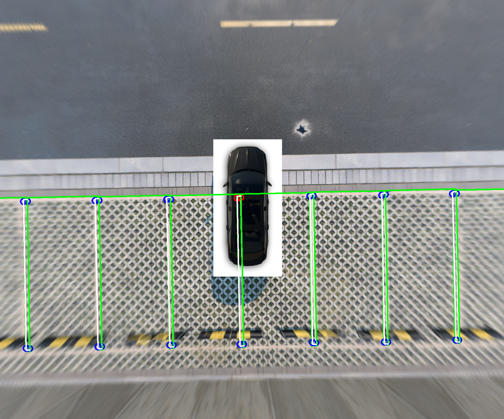
- E:\\DumpData\\res will contain three folders — bev_image, json, and json_image — storing the BEV stitching results, ground-truth JSON data, and the ground-truth JSON data overlaid on the stitched images, respectively. In the overlaid images: blue hollow circles indicate visible interior corner points of parking spaces; red hollow circles indicate occluded interior corner points; green wireframes are the bounding boxes of parking spaces; white wireframes are the bounding boxes of left and right boundary lines.
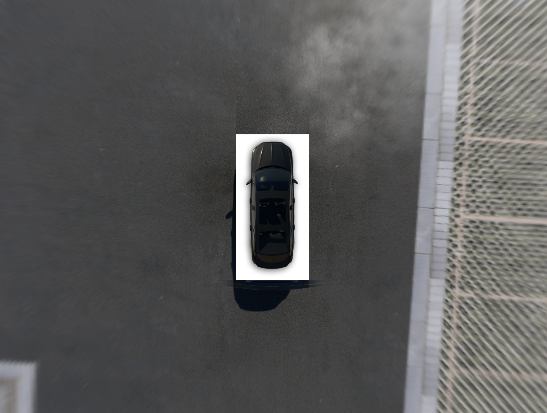
A BEV stitching result example is shown below:
When --show_json_on_img True is used, the JSON results are annotated on the final stitched image, as shown below:
3.3.5 Ground-Truth JSON Data Format Description
3.3.5.1 Coordinate System and Rotation Matrix
The following coordinate systems are defined:
(1)The world coordinate system origin is consistent with the map, with coordinate axes aligned to the map — the rightward direction in the map editing interface is the positive X axis, upward is the positive Y axis, and outward from the screen is the positive Z axis.
(2)The vehicle body coordinate system origin is consistent with the Ego Vehicle preview — located at the midpoint of the line connecting the contact points of the two rear wheels with the ground. The coordinate axes are also consistent with the Ego Vehicle preview: the vehicle heading direction is the positive X axis, left is the positive Y axis, and up is the positive Z axis.
(3)The camera coordinate system origin is consistent with the Ego Vehicle preview. The camera facing direction (forward) is the positive X axis, left is the positive Y axis, and up is the positive Z axis.
(4)In the camera imaging coordinate system, the origin is the upper-left corner, the rightward direction is the positive U axis, and the downward direction is the positive V axis.
All rotation matrices are extrinsic rotation matrices; no additional explanation is given here.
3.3.5.2 BEV Conversion Tool Output Format
After conversion, the Dump data is transformed into BEV images and JSON ground-truth data. The individual sections of the JSON ground-truth data are described below.
(1)Vehicle Information
(2)Camera Information
(3)Parking Space Information
3.3.5.3 Raw Dump Data Format
When implementing a custom BEV stitching algorithm, you will need to start from the raw Dump data for each direction. Inside the Dump output path, each task's folder contains a subfolder for each fisheye camera. Within each camera subfolder, each frame has its own folder containing the following four files:
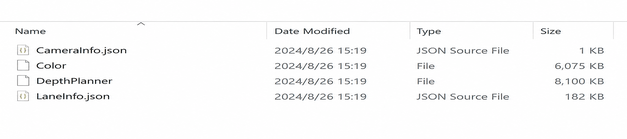
LaneInfo.json is the ground-truth data output by this camera. Its main sections are briefly described below.
(1)Vehicle and Camera Information
Primary vehicle and camera data.
- Parking Space Information
The "laneMark_ParkingSpaces" field in the JSON file contains parking space information.
- Lane Line Information
The "lane_lines" field in the JSON file contains lane line information defined based on the OpenLANE format.
3.3.6 Brief Description of the BEV Stitching Algorithm
The basic principle of BEV stitching is to transform images from four directions using homography matrix computation and project them into a top-down perspective. The basic algorithm workflow can be summarized as: define the target BEV range → calibrate each direction → rectify each directional fisheye camera image → project each directional camera image → smooth the overlap regions → obtain the final BEV stitched image.
Important note: The prerequisite for the four fisheye camera images to stitch into a correct BEV image via homography transformation is that the image content lies in the same plane. Otherwise, objects with elevation may appear as ghosting at the overlap regions between different directional fields of view — this is an inherent limitation of homography transformation and cannot be eliminated. Alternatively, you can change the strategy to avoid ghosting: instead of smoothing the overlap region, directly concatenate by keeping only one direction's result at the seam. However, this will result in an unsmooth appearance and visible jumps at the seam for elevated objects. The choice depends on your specific requirements.
The JSON ground-truth portion primarily involves transforming between different coordinate systems — converting camera coordinate system coordinates from the raw Dump data into the world coordinate system to obtain the final aggregated results. The process is relatively straightforward.
For technical details, you can use homography matrix and BEV as search keywords. They are not elaborated further here.
3.3.7 Special Handling of Anomalous Data
Due to inherent limitations of the BEV stitching algorithm, objects with elevation may appear as ghosting in the stitched result. In some cases, a particular annotation object may be visible from one direction but not from another. For such cases, visibility in the BEV stitched result must be determined based on your specific requirements.
The conversion tool's final JSON output may not match your requirements. In such cases, retrieve the ground-truth data from each directional fisheye camera's raw "LaneInfo.json" and filter and stitch the data according to your own needs.