Object-Level Sensor Details
1. Overview
Object-Level Sensors are an important component of the SimOne simulation platform. Unlike raw-data sensors that output point clouds or images, object-level sensors directly output processed, structured obstacle lists (Object Lists).
SimOne supports the following object-level sensors:
| Sensor Type | Output Data | Key Features | Use Cases |
|---|---|---|---|
| Ideal Sensor | Perfectly accurate obstacle list | No error, supports occlusion culling | Ground truth baseline for validating planning & decision algorithms |
| Camera | Simulated vision-recognition target list | Supports distance/size error models | Testing downstream algorithm robustness based on visual perception |
| LiDAR | Simulated point-cloud-clustered targets | Supports environmental interference and point cloud noise simulation | Testing algorithm performance under adverse weather or sensor jitter |
| Sensor Fusion | Multi-sensor fused results | Simulates multi-sensor spatial-temporal synchronization and fusion logic | Validating early-fusion / late-fusion algorithm performance at the system level |
2. Ideal Sensor
2.1 Overview and Data Output
The ideal sensor simulates an "omniscient" perception capability, returning absolutely accurate obstacle information (vehicles, pedestrians, traffic infrastructure, etc.) within the ego vehicle's detection range.
- Primary Use: Serves as the Ground Truth baseline input for planning & decision algorithms.
- Data Output:
- Physical Properties: position, orientation, bounding box, velocity, acceleration, angular velocity.
- API Access: retrieve the structured list directly via
SimOneAPI:GetSensorDetections.
2.2 Core Parameter Descriptions
Although the ideal sensor outputs ground truth by default, the following parameters allow simulation of physical characteristics (e.g., occlusion) or artificial fault injection (Error Injection).
| ID | Parameter | Description |
|---|---|---|
| 1 | Occlusion Culling | Function: Simulates real-world line-of-sight — automatically filters targets occluded by buildings or preceding vehicles. Configuration: • Enable: Toggle occlusion calculation on/off. • Ratio [0.0–1.0]: Occlusion threshold. E.g., a value of 0.8 means targets that are more than 80% occluded are treated as "invisible" and not output. |
| 2 | Error Simulation | Function: Tests algorithm robustness when sensor data is inaccurate. Note: This feature reuses the LiDAR error model. For specific parameters (position error, velocity error, angle error, etc.), refer to the [4.1 LiDAR — Perception Error] section. |
3. Camera (Object-Level) Simulation
Similar to the LiDAR object-level simulation, the camera object-level simulation is based on the detection results of a real object detection model. The environmental and target influence factors are tuning coefficients derived from real detection results. As the factors affecting a simulation target change, the detection confidence of that target changes accordingly. The perception error primarily adjusts target jitter noise. The object-level camera also supports lane-line simulation, including lane-line jitter and error settings. Factors shared with LiDAR — environmental, occlusion, and perception error — are described above and are not repeated here. The following section covers the target size factor and its impact on the detection score.
3.1 Target Size Influence Factor
This factor reflects the relationship between target size and detection confidence in a real object detection model. When the target size influence factor changes, the detection confidence changes accordingly.
3.2 Configuration
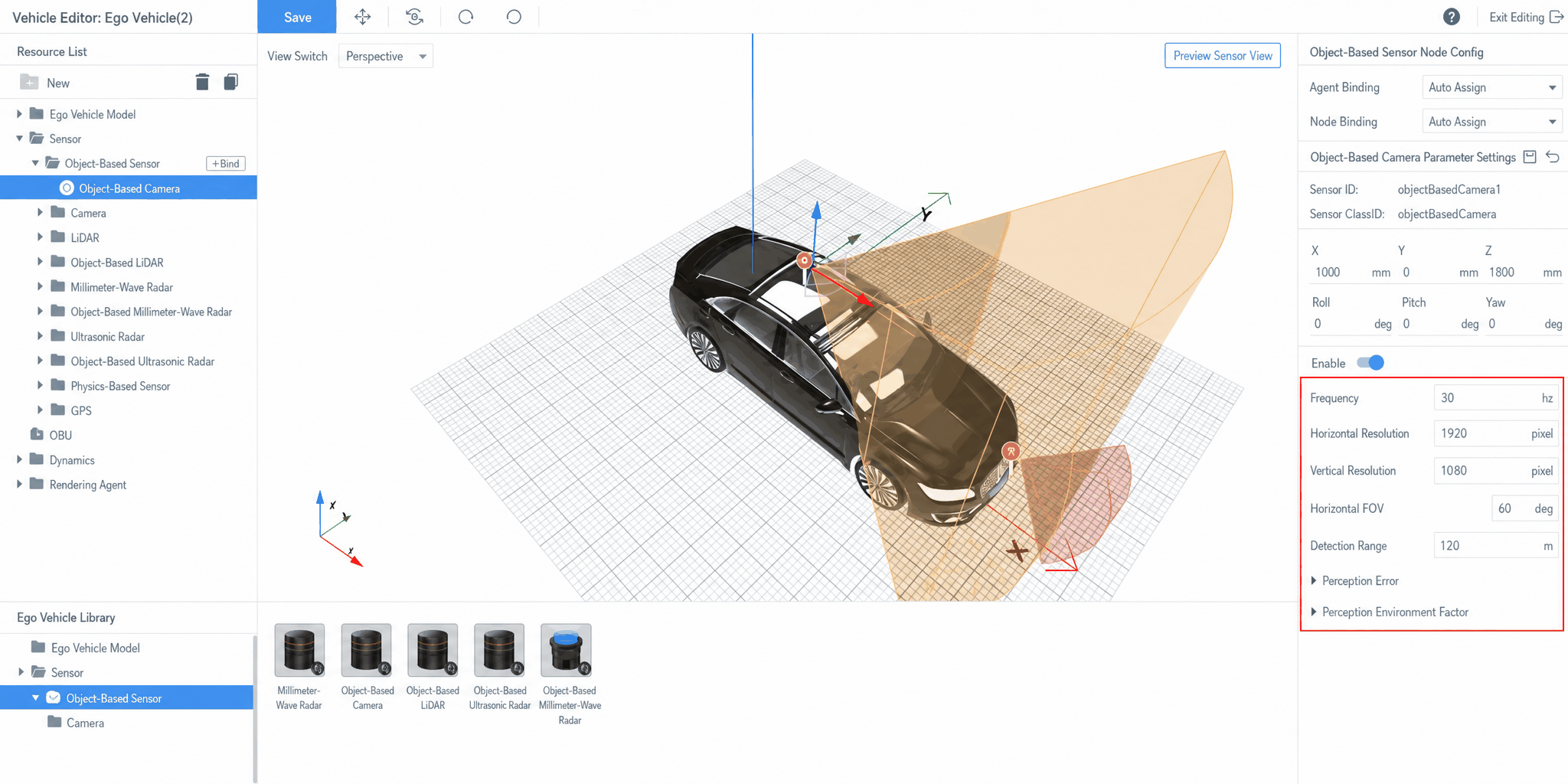
Drag an object-level camera into the viewport and configure the relevant parameters.
4. LiDAR (Object-Level) Simulation
The LiDAR object-level simulation supports adjusting target output via perception environmental influence factors and perception error. The environmental factors consist of environment parameter factors and target parameter factors, primarily simulating how the probability of a target being recognized by a perception algorithm changes as the environment changes. Perception error is used to adjust target jitter noise.
4.1 Perception Error
Perception error includes target position error, target velocity error, and target angle error, primarily simulating the actual jitter of targets in a real environment.
- Target Position Error: The difference between the position measured by the radar and the actual position of the target.
- Target Velocity Error: The difference between the velocity estimated from radar data plus algorithms and the target's actual velocity.
- Target Angle Error: The difference between the target's bearing angle relative to the radar (calculated from radar data plus algorithms) and the true bearing angle.
4.2 Perception Environmental Influence Factors
In LiDAR object-level simulation, targets are divided into six major categories: cars, trucks, buses, two-wheelers, pedestrians, and traffic signs. Two-wheelers include bicycles and electric scooters; pedestrians include those on foot and those riding; traffic signs include road signs, traffic lights, and temporary roadside facilities. For each category, 3 influence factors adjust the detection confidence, and a confidence threshold is set to determine whether a target is detected (used for missed-detection rate calculation). Additionally, environmental influence factors for special weather (rain, snow, fog) are supported.
4.2.1 Environmental Influence
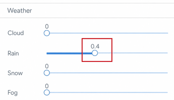
Environmental influence factors currently support rain, snow, and fog. When users set the environment in the test case configuration, the corresponding rain/snow/fog factor takes effect. The default value is 0.5. As weather conditions worsen (e.g., heavier rain), the laser beams are more strongly absorbed and scattered by the environment, reducing the number of points hitting an object compared to clear weather. The simulated output probability for that target decreases progressively; when the probability falls below the target's threshold, the simulation stops outputting that target's information.
4.2.2 Target Influence Factors
In LiDAR object-level simulation, the six target categories are: cars, trucks, buses, two-wheelers, pedestrians, and traffic signs. For each category, orientation, occlusion, and distance influence factors are configured to simulate perception scores under these three conditions, along with a confidence threshold to determine whether a target is detected.
4.2.2.1 Orientation Influence Factor
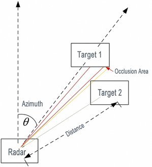
Orientation is defined as the angle between the ego vehicle's forward direction and the radial direction from the ego vehicle to the target, as shown in the diagram below. As a target's orientation changes, the number of laser points hitting the object changes, which in turn affects the perception algorithm's detection score and thus the simulated output confidence.
4.2.2.2 Occlusion Influence Factor
Occlusion is defined as the ratio of laser points actually hitting the target to the number of points that would hit it with no occlusion, calculated using a sampling algorithm. Greater occlusion means fewer points hit, resulting in a lower perception score and lower output probability.
4.2.2.3 Distance Influence Factor
Distance is defined as the distance from the LiDAR center to the target center. As the distance increases, the target is farther from the radar. Points at longer distances are generated at larger vertical angles, so the spacing between points increases and fewer points hit the same object. As a result, the simulated output probability decreases progressively with increasing distance.
4.2.2.4 Confidence Threshold
The confidence threshold is primarily used to adjust the false detection rate.
When the simulated output probability falls below the confidence threshold, target information is not output.
Conversely, when the probability is above the threshold, target information is output normally.
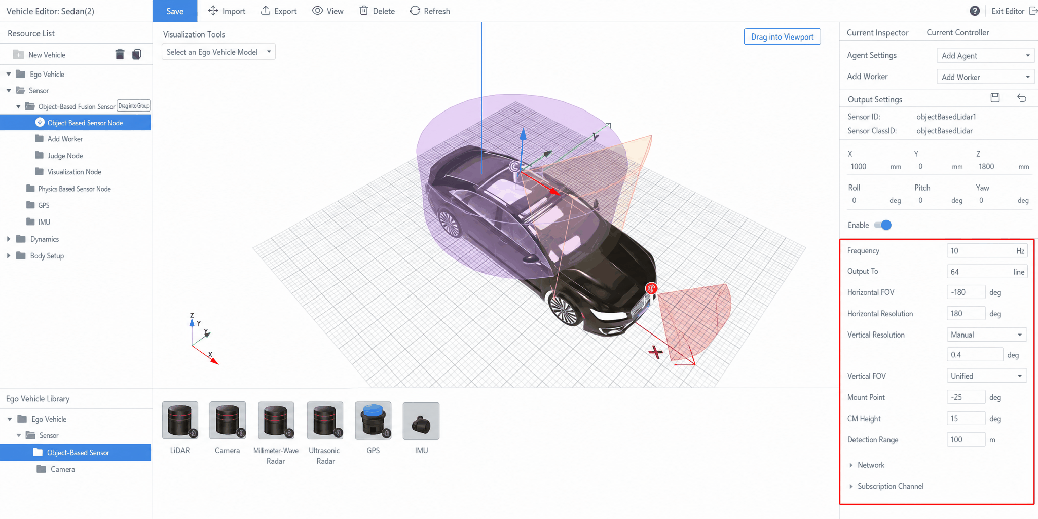
4.3 Configuration
Drag an object-level LiDAR into the viewport and configure the relevant parameters.
5. Sensor Fusion (Object-Level) Simulation
Similar to LiDAR and camera object-level simulations, the fusion object-level simulation is based on the detection results of a real object detection model. The environmental and target parameter factors are tuning coefficients derived from real detection results. As the factors affecting a simulation target change, the detection confidence changes accordingly. Perception error primarily adjusts target jitter noise. Factors shared with LiDAR — environmental, occlusion, and perception error — are described above and are not repeated here. The following sections cover the impact of target position and target 3D size on the detection score.
5.1 Target Position Influence Factor
This factor reflects the relationship between target position and detection confidence in a real object detection model. When the target position influence factor changes, the detection confidence changes accordingly.
5.2 Target 3D Size Influence Factor
This factor reflects the relationship between target 3D dimensions and detection confidence in a real object detection model. When the 3D size influence factor changes, the detection confidence changes accordingly.
5.3 Configuration
The ego vehicle configuration for fusion object-level sensors differs from that for radar and camera object-level sensors. The procedure is as follows:
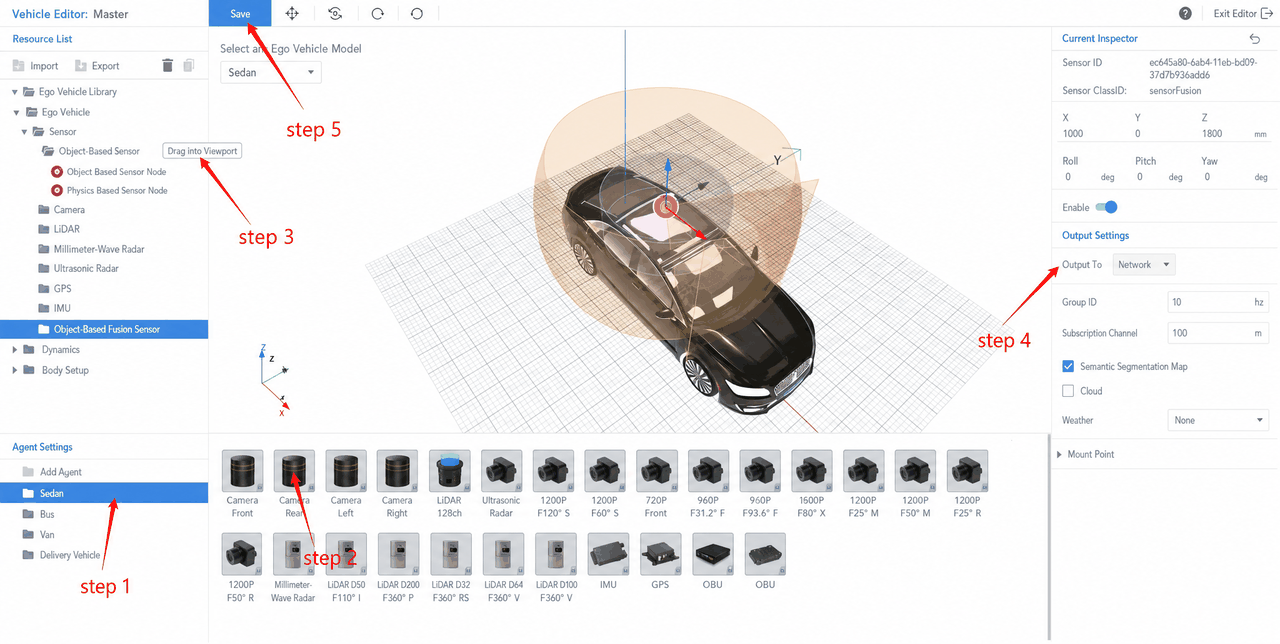
After selecting the ego vehicle, you can configure the fusion object-level sensor:
- Select the sensor resource library.
- Drag object-level sensors into the ego vehicle.
- Add a sensor fusion group.
- Select the object-level sensors to include in the fusion group.
- Save the configuration.
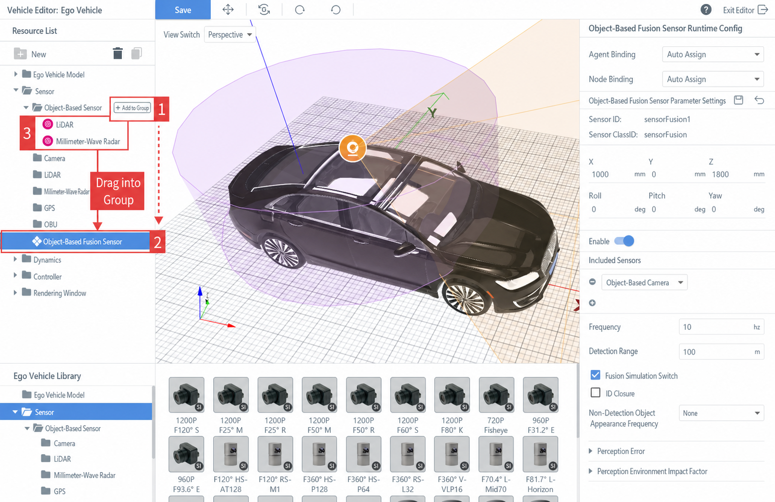
5.4 Creating a Sensor Fusion Group
Drag multiple object-level sensors into the viewport; the relevant sensors will be automatically added to the object-level fusion sensor.
Sensor Fusion Group
Automatically analyzes and synthesizes information and data from multiple sensors or sources according to defined criteria, to complete the perception task required by the decision algorithm.
Add Fusion Group
In the resource list on the left, click Resource List → click the + Fusion Group button to the right of the Object-Level Sensors folder to add another fusion group under the resource list.
After adding a fusion group, drag object-level sensors into the fusion group to combine them into another sensor group.
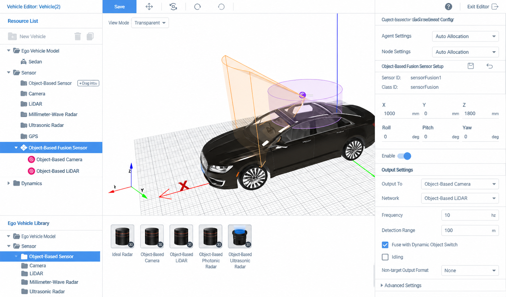
5.5 Setting Fusion Sensor Group Parameters
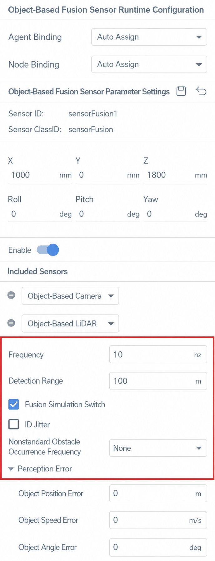
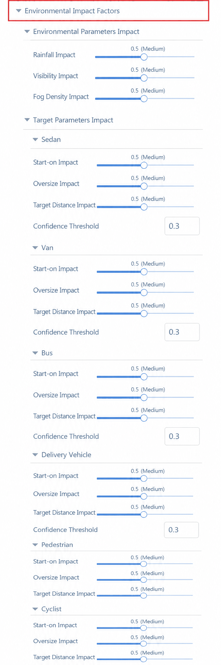
Select the object-level fusion sensor in the left resource list to configure its parameters in the Sensor Parameter Settings panel on the right, including fusion frequency, detection range, ID jitter inclusion, non-standard obstacle frequency, perception error, and environmental perception factors.