Camera Details
1. Overview
- Simulation Foundation: Constructs a virtual 3D model of the real world with physically accurate materials, textures, colors, and optical properties; uses physically-based rendering (PBR) and physically-based lighting to conserve light energy and reproduce real-world imaging.
- Key Parameters and Coordinate Transforms: Core parameters include extrinsics (mounting state), intrinsics (optical inherent properties), and distortion parameters (correcting geometric distortion). These are converted into projection matrices to ensure accurate transforms across "World Coordinate System → Camera Coordinate System → Image Coordinate System → Pixel Coordinate System", producing output that matches a real camera.
- Scene and Weather Support: Leverages SimOne's diverse simulation scenes to simulate complex weather and lighting conditions, including custom time-of-day, illumination, solar elevation angle, and cloud/rain/snow/fog/dust settings. See Configure Environment (Weather/Time) for details.
- Data Output and Testing Capability: Outputs per-frame RGB images, depth maps, 2D/3D bounding boxes, semantic/instance segmentation maps, and other raw data; supports SIL (Software-in-the-Loop) and HIL (Hardware-in-the-Loop) testing for camera recognition algorithms, and outputs structured ground-truth data (ego vehicle state, obstacle information) for algorithm evaluation.
2. Appendix: Simulation Parameter Reference
2.1 Input Parameters
These parameters simulate a real hardware camera to make the images generated in the virtual scene closely match those captured by a real camera.
2.1.1 Basic Information
| No. | Parameter | Definition |
|---|---|---|
| 1 | Frequency | Frame rate (refresh rate) of the image output. Affects image update speed and computational load. |
| 2 | Horizontal Resolution | Number of pixels in the horizontal direction. |
| 3 | Vertical Resolution | Number of pixels in the vertical direction. |
| 4 | Horizontal FOV | Horizontal field of view angle, affecting image width and distortion. |
| 5 | Detection Range | Maximum distance at which the camera can recognize or output data. |
| 6 | Trigger Time | Image capture trigger delay, used to synchronize multi-sensor output. |
2.1.2 Intrinsics
| No. | Parameter | Definition |
|---|---|---|
| 1 | Focal Length | Lens focal length, determining the field of view and imaging scale. A longer focal length gives a narrower field of view and larger distant objects. |
| 2 | Exposure Compensation | Adjusts the brightness of simulated images; positive values increase brightness, negative values decrease it. |
| 3 | Color Temperature | Represents the warm/cool tone of the overall image. Lower values shift toward blue; higher values shift toward yellow. |
| 4 | Tint | Adjusts the overall color bias. Lower values shift toward green; higher values shift toward magenta. |
| 5 | Saturation | Controls color vividness. Higher values produce more vivid colors; lower values produce more muted tones. |
| 6 | Contrast | Controls the difference between bright and dark areas. Higher values produce more visible tonal gradations. |
| 7 | Sharpness | Adjusts edge sharpness. Moderate sharpening enhances edge clarity; excessive values may introduce noise. |
| 8 | Gamma (Brightness) | Controls the non-linear brightness response curve; typically set to 2.2. Higher values produce a darker overall image. |
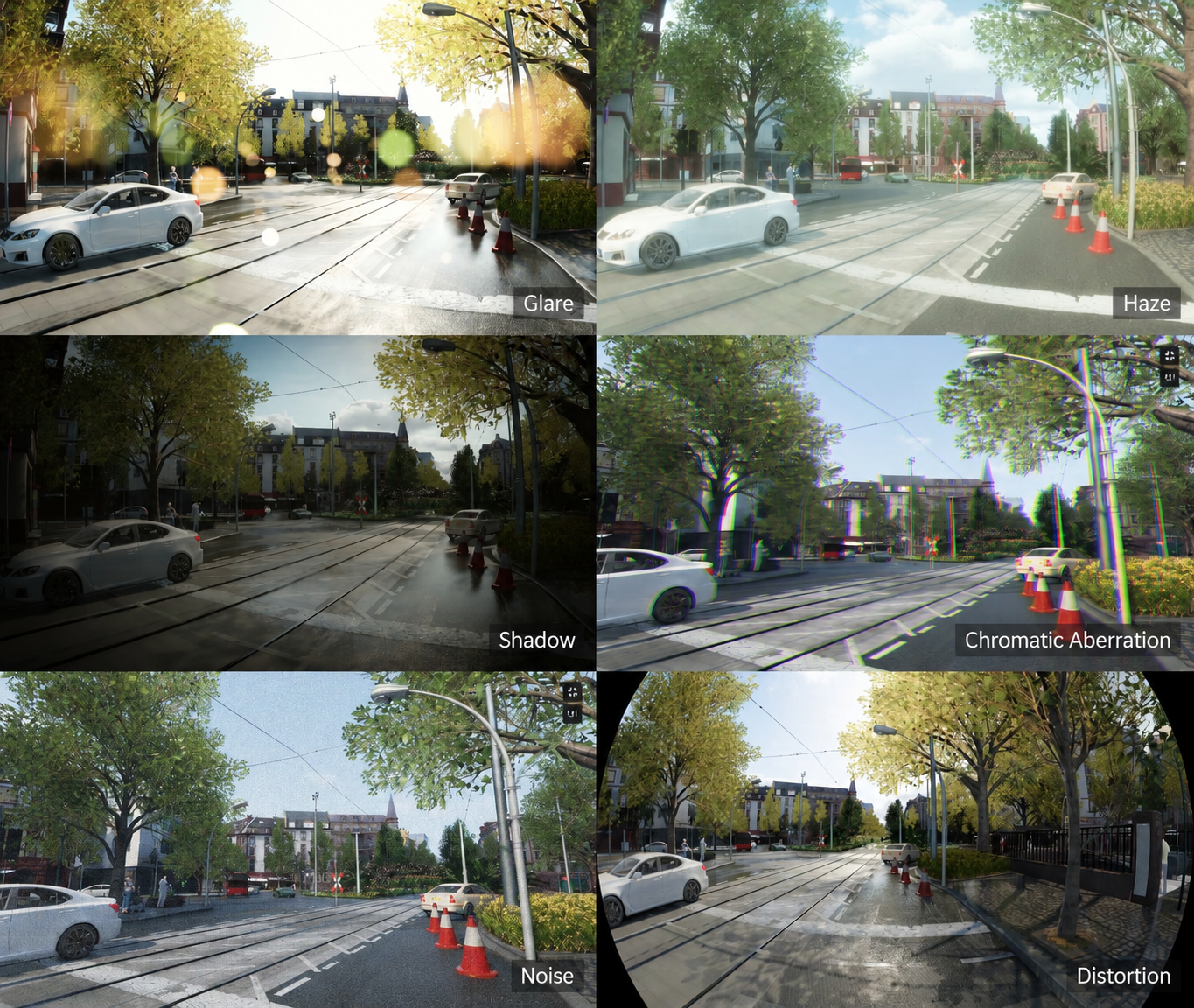
| 9 | Lens Flare | Reflections or light spots generated when the lens faces a strong light source directly, simulating physical lens glare. |
| 10 | Bloom | Overflow of light from bright areas, making highly lit objects appear soft and glowing. |
| 11 | Vignette | An optical effect where image edges are darker than the center, caused by lens structure or obstruction. |
| 12 | Motion Blur | Image blur caused by object or camera motion during exposure. Higher values produce more noticeable blur. |
| 13 | Chromatic Aberration | Color fringing on edges caused by differences in refraction index across wavelengths. |
| 14 | Noise | Simulates random noise from the imaging sensor. Higher values produce a grainier image. |
| 15 | Lens Dirt | Simulates visual effects from lens contamination or weather: • Dirt (light / medium / heavy) • Frost (light / medium / severe) • Water drops (few / medium / many) • Ice (few / medium / heavy) |
| 16 | Raw Pixel Mode | Output pixel arrangement mode, determining the raw Bayer image format. Supported: RGB, BGGR, RGGB, RCCB, RCCC, GRBG |
| 17 | Raw Data Type | Specifies the raw data output format. • Standard output • Raw12 output (high-precision mode) |
2.1.3 Distortion
Correction parameters for geometric distortion caused by lens manufacturing tolerances, assembly errors, or optical structure. Common distortion types include:
- Radial Distortion: Causes straight lines to curve toward or away from the center, mainly controlled by K1, K2, K3, K4, K5, K6.
- Tangential Distortion: Caused by the lens not being perfectly parallel to the image plane, mainly controlled by P1, P2.
- Thin Prism Distortion: Generally negligible, adjustable via S1, S2.
| No. | Parameter | Definition |
|---|---|---|
| 1 | Focal Length Fx, Fy | Focal lengths in the horizontal and vertical directions of the image plane (usually related to pixel size). |
| 2 | Principal Point Cx, Cy | Position of the image center (principal point) in pixel coordinates. Usually close to the image center. |
| 3 | Radial Distortion Coefficients K1, K2, K3, K4, K5, K6 |
Control the degree of inward (barrel) or outward (pincushion) bending. Negative values typically indicate barrel distortion; positive values indicate pincushion distortion. |
| 4 | Tangential Distortion Coefficients P1, P2 | Control asymmetric distortion caused by lens tilt (image shift in one direction). |
| 5 | Thin Prism Distortion Coefficients S1, S2 | Simulates slight bending of light rays passing through lens edges; typically 0 and can be ignored. |
2.1.4 Fisheye
| No. | Parameter | Definition |
|---|---|---|
| 1 | K1, K2, K3, K4 | Radial Distortion Coefficients. Describe the distortion at the edges of fisheye lens images. Mathematical expression: \(r_d = r \left(1 + K_1 r^2 + K_2 r^4 + K_3 r^6 + K_4 r^8 \right)\) where \(r\) is the ideal projection radius and \(r_d\) is the distorted radius. Typically obtained via camera calibration. Positive values indicate barrel distortion (edges expand outward); negative values indicate pincushion distortion (edges contract inward). |
| 2 | Projection Model: Stereographic | Mathematical relationship: \(r = 2f \tan\left(\frac{\theta}{2}\right)\) Features: Good conformality, natural distortion, suitable for panoramic stitching and rendering. |
| 3 | Projection Model: Equidistant | Mathematical relationship: \(r = f \theta\) Features: Angle and image radius are linearly proportional; simple to compute; widely used in SLAM and visual measurement. |
| 4 | Projection Model: Equisolid Angle | Mathematical relationship: \(r = 2f \sin\left(\frac{\theta}{2}\right)\) Features: Equal solid angles map to equal areas; commonly used in photography lenses and VR cameras for high visual realism. |
| 5 | Projection Model: Orthographic | Mathematical relationship: \(r = f \sin(\theta)\) Features: Low distortion in the center, significant compression at the edges; often used for simulation displays or engineering scenarios. |
2.1.5 Perception Error
Perception error includes target position error, target velocity error, and target angle error, primarily used to simulate the actual jitter of targets in a real environment.
| No. | Parameter | Definition |
|---|---|---|
| 1 | Target Position Error | The difference between the position measured by the camera perception system and the actual position of the target. Typically caused by image resolution, calibration accuracy, and detection algorithm errors; used to simulate position deviations caused by jitter, occlusion, or insufficient recognition precision. |
| 2 | Target Velocity Error | The difference between the target velocity estimated from camera output data via algorithms and the actual target velocity. Reflects the accuracy of velocity estimation algorithms; used to simulate velocity fluctuations caused by sensor sampling rate, latency, or noise. |
| 3 | Target Angle Error | The difference between the bearing angle of the target relative to the camera (calculated from camera data plus algorithms) and the true bearing angle. Reflects the system's deviation when detecting target pose or angle; used to simulate inaccurate angular recognition, calibration errors, or dynamic jitter. |
2.2 Output Settings
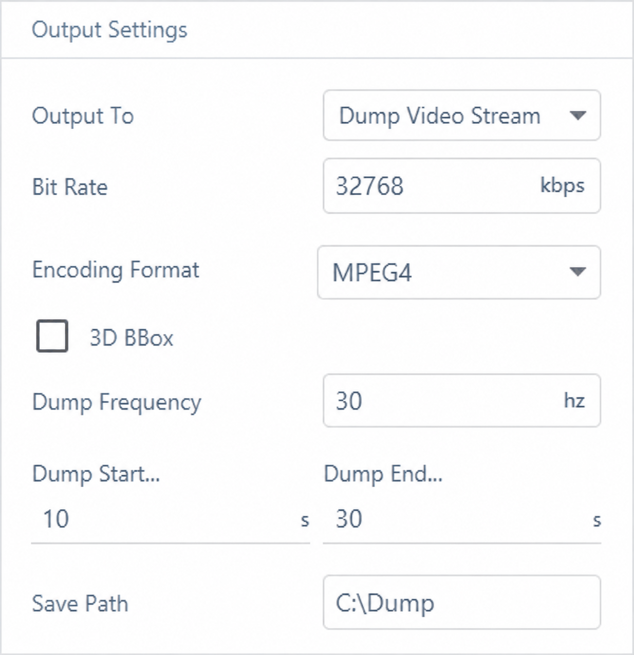
Three output modes are supported: Network, Dump, and Dump Video Stream.
2.2.1 Output to [Network]
| No. | Parameter | Definition |
|---|---|---|
| 1 | Raw Data | Whether to output the camera's raw image data (uncompressed/unencoded). When enabled, outputs data closest to the raw sensor signal, facilitating algorithm debugging and validation. |
| 2 | Encoding Format | Sets the data encoding method for image output. Different encodings affect quality, bandwidth, and processing performance: • RGB: Uncompressed standard three-channel format, retains full color information, large data size, suitable for high-precision algorithm validation; • JPEG: Lossy compression, small file size, suitable for bandwidth-limited or storage-constrained scenarios; • H.265: High-efficiency video coding (HEVC), supports continuous-frame compressed transmission, low bandwidth usage, commonly used for real-time video streams. |
| 3 | Subscription Channel | Configures the network subscription address and port number for the data stream. Defines the network interface for clients to receive camera data; supports UDP protocol. |
| 4 | RLE Semantic Segmentation | Whether to output semantic segmentation results using RLE (Run-Length Encoding) compression. RLE is a lightweight lossless encoding that effectively reduces semantic image data size. |
2.2.2 Output to [Dump]
| No. | Data Type | Definition and Use | Illustration |
|---|---|---|---|
| 1 | RGB Image | Standard three-channel color image (Red, Green, Blue) output by the camera. Used for visual perception, object detection, image recognition, etc. Rendered scene image identical to that captured by a vehicle's front-facing camera. |  |
| 2 | Semantic Segmentation Map | Classifies each pixel in the scene into a semantic category (e.g., road, pedestrian, vehicle, building). Used for training and validating semantic segmentation algorithms. Each pixel color represents a semantic category. |  |
| 3 | Depth Map | Represents the distance (depth value) of each pixel from the camera, in meters. Used for 3D reconstruction, obstacle avoidance, and perception fusion. Brighter colors indicate greater distance. |  |
| 4 | Instance Segmentation Map | Extends semantic segmentation to distinguish individual instances of the same category (e.g., two separate vehicles). Used for precise object detection and recognition. Different instances of the same category are shown in different colors. |  |
| 5 | Lane Lines (OpenLane) | Outputs lane-line annotation data in OpenLane dataset format, used for lane detection and path planning algorithm validation. Supports visualization and algorithm evaluation interfaces. |
 |
| 6 | Normal Map | Represents the surface normal direction (i.e., surface orientation) of each pixel in the scene. Used for lighting simulation, material recognition, and 3D perception optimization. The R, G, B channels represent the X, Y, Z normal components respectively. |  |
| 7 | Ground Truth | Real annotation data for algorithm evaluation, including object category, position, pose, velocity, etc. Can serve as a baseline for model training or performance assessment. • 3DBBox: 3D bounding box • Vehicle Rect Threshold: vehicle occlusion threshold (bounding box) • Vehicle Pix Threshold: vehicle occlusion threshold (pixels) • Pedestrian Rect Threshold: pedestrian occlusion threshold (bounding box) • Pedestrian Pix Threshold: pedestrian occlusion threshold (pixels) • Bike Rect Threshold: bicycle occlusion threshold (bounding box) • Bike Pix Threshold: bicycle occlusion threshold (pixels) • Other Rect Threshold: other objects occlusion threshold (bounding box) • Other Pix Threshold: other objects occlusion threshold (pixels) |

|
2.2.3 Output to [Dump Video Stream]
| No. | Parameter | Description |
|---|---|---|
| 1 | Bit Rate | Video quality control — higher values produce clearer images and larger file sizes |
| 2 | Encoding Format | Video compression format; MPEG4 is common for general video files, while H.264 and H.265 are widely used high-efficiency codecs |
| 3 | 3D BBox | Optional; when checked, 3D bounding boxes are overlaid on the video |