V2X Technology and Simulation
1. Introduction to V2X
V2X (Vehicle-to-Everything) refers to the technology that enables information exchange and communication between vehicles and infrastructure, other vehicles, pedestrians, and other road participants. Here, "V" stands for vehicle, and "X" represents any type of communication with other road participants.
1.1 Purpose
The purpose of V2X technology is to improve traffic efficiency and safety by enabling real-time information exchange and coordination to reduce traffic accidents, alleviate congestion, and lower pollution.
1.2 Technology Classification
V2X is typically based on wireless communication and internet technologies, and includes various communication types such as Vehicle-to-Vehicle (V2V), Vehicle-to-Infrastructure (V2I), Vehicle-to-Pedestrian (V2P), and Vehicle-to-Network (V2N).
1.1 Single-Vehicle Intelligence
1.1.1 Working Principles
Single-vehicle intelligence operates through sensor detection and localization, computational decision-making, and control execution.
- Sensor Detection and Localization: Single-vehicle intelligence uses onboard sensors to detect and localize the surrounding environment.
- Computational Decision-Making: Sensor data is analyzed and processed to identify targets, predict behavior, perform global path planning, local path planning, and instantaneous action planning, determining the vehicle's current and future trajectory.
- Control Execution: Control execution primarily includes vehicle motion control and human-machine interaction, generating control signals for actuators such as motors, throttle, and brakes.
1.1.2 Current Status
Based on the L0–L5 autonomous driving levels defined by the Society of Automotive Engineers (SAE):
- ADAS (Advanced Driver Assistance Systems) remains the dominant form.
- L2 is at the commercialization and deployment stage, but market penetration and application scale remain relatively small.
- L3, L4, and higher levels remain primarily in experimental and regional demonstration phases; large-scale commercial deployment will require more time.
Autonomous Driving Level Classification
The SAE L0–L5 autonomous driving levels are defined as follows:
- L0 (No Automation): No automation; fully driver-operated.
- L1 (Driver Assistance): Basic automation systems such as cruise control and automatic braking, but the driver must continuously monitor and control the vehicle.
- L2 (Partial Automation): More advanced automation including lane keeping and automatic lane changes, assisting the driver to some extent, but the driver must still continuously monitor and control the vehicle.
- L3 (Conditional Automation): The vehicle can drive fully autonomously under certain conditions, but the driver must take over under other conditions.
- L4 (High Automation): The vehicle can drive fully autonomously in most scenarios, but driver intervention may be required in some special situations.
- L5 (Full Automation): The vehicle can drive fully autonomously under any road and weather conditions without driver intervention.
1.1.3 Limitations
Single-vehicle intelligence faces several limitations: safety remains a significant challenge, long-tail problems restrict the operational design domain, and the economic viability of equipping vehicles with multiple expensive sensors has not yet been fully resolved.
Under current autonomous driving capabilities, it is not yet possible to strike a balance between safety, operational domain restrictions, and economics — a fundamental improvement in autonomous driving capability is needed. One approach to resolving these issues is vehicle-road cooperative technology.
1.2 Vehicle-Road Cooperation
Vehicle-Road Cooperation (V2I — Vehicle Infrastructure Integration) greatly expands a vehicle's perception range and capability through information exchange, cooperative perception, and cooperative decision-making and control. By making roads intelligent using RSUs and roadside MEC, it fundamentally addresses the technical bottlenecks of single-vehicle autonomous driving. The combination of OBU and RSU provides additional redundant information to individual vehicles, ensuring driving safety.
1.2.1 Development Stages
Vehicle-road cooperative autonomous driving evolves through three main stages:
- Information Exchange and Cooperation: Direct communication between vehicle OBU and roadside RSU, enabling information exchange and sharing between vehicles and roads.
- Cooperative Perception: Sharing of information from both roadside and onboard sensors.
- Cooperative Decision-Making and Control: Using perception information from both vehicle and roadside, and leveraging roadside decision-making to control vehicles and other infrastructure across the entire road, improving traffic efficiency and safety.
Vehicle-road cooperation and single-vehicle autonomous driving are not two independent components — they complement each other in achieving autonomous driving on public roads.
From a composition perspective, vehicle-road cooperation includes both intelligent vehicles (single-vehicle intelligence) and intelligent roads.
Intelligent roads require:
- Roadside sensors (millimeter-wave radar, cameras, LiDAR, etc.)
- Roadside communication units (Roadside Unit RSU, cellular base stations)
- Roadside edge computing infrastructure (Multi-access Edge Computing MEC, cloud platforms)
- Roadside real-time kinematic RTK (GNSS correction)
- Roadside signs, traffic signals, and their control units
Accordingly, the wave of developing V2X-based connected vehicles to transition autonomous driving from autonomous control to cooperative control and improve driving safety is gaining momentum.
2. V2X Standards
The deployment of vehicle-road cooperative autonomous driving solutions requires national standards, new infrastructure, and legal and regulatory support. It is the product of intelligent vehicles and smart roads. Different government and industry bodies have established various standards and regulations for different stages of autonomous driving.
Domestic vehicle-road cooperation standards include:
T/CSAE 53-2017 Cooperative Intelligent Transportation Systems – Application Layer and Application Data Exchange Standards for Vehicular Communication Systems
T/CSAE 53-2020 Cooperative Intelligent Transportation Systems – Application Layer and Application Data Exchange Standards for Vehicular Communication Systems
T/CSAE 157-2020 Cooperative Intelligent Transportation Systems – Application Layer and Application Data Exchange Standards for Vehicular Communication Systems (Phase 2)
T/CSAE 158-2020 Data Interaction Content for High-Level Automated Driving Based on Vehicle-Road Cooperation
T/CSAE 156-2020 General Technical Requirements for Automated Valet Parking Systems
YD-T 3707-2020 LTE-Based Vehicular Wireless Communication Technology – Network Layer Technical Requirements
YD-T 3755-2020 LTE-Based Vehicular Wireless Communication Technology – Technical Requirements for Roadside Equipment Supporting Direct Communication
YD-T 3710-2020 LTE-Based Vehicular Wireless Communication Technology – Message Layer Test Methods; Technical Requirements for Intelligent Connected Vehicle Test Sites
Ministry of Industry and Information Technology of the People's Republic of China: LTE-Based Vehicular Wireless Communication Technology – Technical Requirements for Security Certificate Management Systems
LTE
Long-Term Evolution / Mobile Communication Standard
LTE (Long-Term Evolution) is a mobile communication standard and one of the primary technologies for 4G networks. It was developed by 3GPP (3rd Generation Partnership Project) and has received broad recognition and support across the global mobile communications industry. Compared to 3G networks, LTE's main advantages include higher data transfer rates and lower latency, enabling it to better support high-speed mobile communication and multimedia data transmission — such as HD video, audio, and online gaming. LTE also offers better spectrum efficiency and signal coverage, providing more stable and high-quality wireless communication over a wider area.
3. V2X Development History
Starting from the 2018 V2X "Three Cross" demonstration — crossing communication modules, terminal types, and vehicle OEMs — to the 2019 C-V2X "Four Cross" interoperability demonstration that added cross-chip modules, the pioneer demonstrations gave more people a firsthand experience of the potential of C-V2X.
The "New Four Cross" initiative builds on the foundation of the "Three Cross" and "Four Cross" by further deepening the testing and validation of C-V2X technologies and standards in response to evolving technical and industry requirements. It incorporates HD maps and high-precision positioning, and combines domestic cryptographic algorithms. Location-related information broadcast by vehicles and roadsides is first offset and then encrypted, exploring technical solutions to the map and positioning regulatory challenges facing C-V2X. It also adopts an entirely new digital certificate format and introduces new elements such as a cloud control platform, V2X information display, and location situational awareness platforms.
4. Introduction to Application Layer Standards
The application layer standard Cooperative Intelligent Transportation Systems – Application Layer and Application Data Exchange Standards for Vehicular Communication Systems defines the basic applications and fundamental requirements for vehicular communication systems in cooperative intelligent transportation. It specifies the application layer data dictionary, data exchange standards, and interface specifications.
The LTE-based vehicular direct communication system enables intelligent coordination among vehicles, infrastructure, and pedestrians through information exchange, achieving intelligent cooperation between vehicles and infrastructure, vehicle-to-vehicle, and vehicle-to-pedestrian communication. The onboard communication system enables information exchange between different subsystems of intelligent transportation. By communicating directly with every participant in the transportation system, the onboard communication system can provide effective information support for applications including improving road safety, enhancing traffic efficiency, and delivering various information services.
The figure below shows the architecture of a Vehicle-to-RSU (V2I) direct communication system. For an RSU device, it typically consists of the following subsystems:
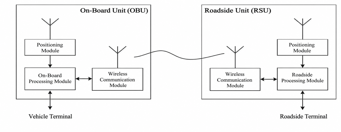
As shown in the figure, a real-world V2X deployment requires at least an OBU (On-Board Unit) and an RSU (Roadside Unit). Simulating V2X means simulating the communication process and data between OBU and RSU. Each module also includes a communication sub-module, an onboard processing module, and a positioning module.
5. Overview of V2X Simulation
SimOne V2X simulation leverages SimOne's strengths: WorldEditor is used to edit and reconstruct Opendrive-format urban road information; SCENARIO Editor and traffic flow simulation software generate dynamic elements — vehicles, pedestrians, traffic signals — based on road network data; and rich roadside and onboard sensor resources are provided. These resources are essential components of the data that V2X sends and receives.
5.1 Application Scenarios
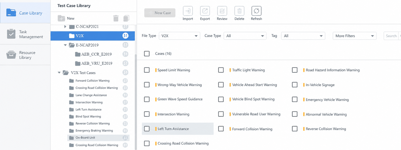
SimOne's application layer is developed in accordance with the CSAE standard Cooperative Intelligent Transportation Systems – Application Layer and Application Data Exchange Standards for Vehicular Communication Systems (2017, 2020), providing 16 application scenarios (excluding proximity payment) and convenient test case customization features.
The figure below shows the V2X test cases supported by SimOne:
5.2 Application Messages
At the application layer, SimOne provides the basic DataElement data elements, DataFrame data structures, and Message communication messages, including BSM (Basic Safety Message), RSI (Roadside Safety Information), RSM (Roadside Monitoring), SPAT (Signal Phase and Timing), and MAP (Map) messages.
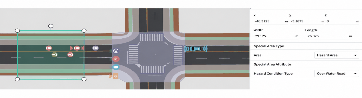
The figure below shows a SimOne V2X scenario:
- BSM (Basic Safety Message): For each vehicle and pedestrian in the scenario, the OBU switch state can be set to generate Basic Safety Messages (BSM).
- RSI (Roadside Safety Information): Using SimOne's scenario test case editing capabilities, special status and special zone triggers are configured, and roadside messages (RSI) are generated in combination with road sign and speed limit information obtained through the HDMap API.
- RSM (Roadside Monitoring): Roadside millimeter-wave radar, LiDAR, cameras, and fusion sensors are configured along with their connection relationships to the roadside RSU and between sensors. Roadside safety messages (RSM) are generated based on the perception data from roadside sensors.
- SPAT (Signal Phase and Timing): Signal phase and timing messages (SPAT) are generated based on the pre-configured signal timing of traffic lights.
- MAP: Map messages (MAP) are generated based on the OpenDRIVE map and the HDMap API.
5.3 Standard Test Case Simulation
SimOne provides standard test case simulation for vehicles, comprehensively accounting for vehicles, buildings, and weather conditions in the vehicle's environment. It supports output of simulated data transfer rate information based on 4G/5G networks, and allows access to the native ASN.1-encoded V2X binary data through the API.
5.4 Testing Modes
Throughout the autonomous driving algorithm development process, various testing phases are required. Simulation testing specifically includes Software-in-the-Loop (SIL), Hardware-in-the-Loop (HIL), and Vehicle-in-the-Loop (VIL) stages. Some phases also require V2X-in-the-loop simulation testing, driving simulator simulation, and other tools.
- SIL — Software-in-the-Loop: SimOne-based software-in-the-loop testing for algorithm development and validation during the concept phase. Developers conduct thorough simulation testing early in the ADAS/AD algorithm development and modeling stage, providing technical validation for subsequent work.
- HIL — Hardware-in-the-Loop: Using SimOne, multiple perception signals are output to a real domain controller platform. Combined with millimeter-wave radar target simulators and multi-channel video injection systems, radar RF signals and video stream signals are simulated and generated to thoroughly test the domain controller hardware and software system, validating whether the hardware platform and internal perception and planning/control algorithms meet test requirements. This approach is an indispensable, safe, and efficient testing method during the autonomous driving product development and testing phase.
- V2X Device-in-the-Loop — HIL: Addressing the testing needs of V2X application algorithms, SimOne's virtual simulation software is combined with RF communication in a joint simulation approach, providing a complete end-to-end V2X application scenario HIL test system. This solution supports completing application scenario simulation and communication environment simulation testing in a laboratory environment, greatly accelerating the V2X R&D validation process.
- VIL — Vehicle-in-the-Loop: Including both laboratory VIL and test site VIL variants, this is an important testing method before vehicle mass production. By injecting virtual simulation scenarios into real vehicles, a wide range of regular and hazardous scenarios can be tested, reducing reliance on physical test sites, real traffic, and test vehicles, lowering the difficulty and risk of real-vehicle testing, improving test efficiency, and reducing test costs.